PID Setting for drifting axis
03 Nov 2016 10:20 #82369
by Chre9
PID Setting for drifting axis was created by Chre9
Hey guys,
a colleague and I are currently repairing a milling machine ("Heller CNC PFH 10-1000"). We are using LinuxCNC 2.7.7 and the engines are controled by MESA Cards (5i20, 7i37 TA, 7i48) with a svst6_6_7i48 firmware.
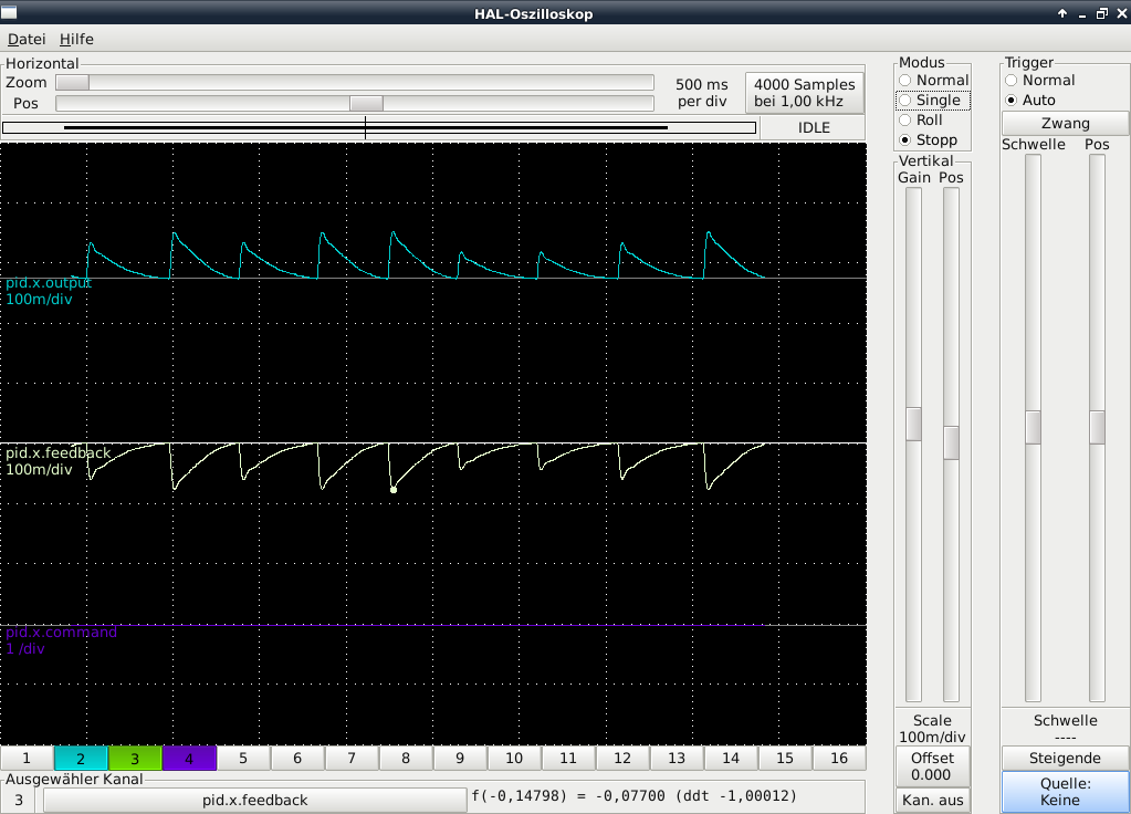
The problem we are facing is, that LinuxCNC tries to compensate the drifting of the x- and y-axis with lots of short peaks of voltage in the output, so the machine starts to cog while holding its position or moving against the drifting direction. Moving the axis in drifting direction in not a problem. You can see the voltage output signal in the attached picture.
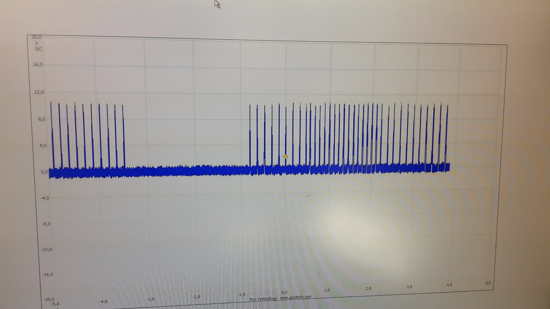
We have been trying to figure out the correct PID values to fix this, but couldn't really. So we would appreciate your help. If you have problems understanding or need further information, please ask.
Thanks in advance!
a colleague and I are currently repairing a milling machine ("Heller CNC PFH 10-1000"). We are using LinuxCNC 2.7.7 and the engines are controled by MESA Cards (5i20, 7i37 TA, 7i48) with a svst6_6_7i48 firmware.
The problem we are facing is, that LinuxCNC tries to compensate the drifting of the x- and y-axis with lots of short peaks of voltage in the output, so the machine starts to cog while holding its position or moving against the drifting direction. Moving the axis in drifting direction in not a problem. You can see the voltage output signal in the attached picture.
We have been trying to figure out the correct PID values to fix this, but couldn't really. So we would appreciate your help. If you have problems understanding or need further information, please ask.
Thanks in advance!
Please Log in or Create an account to join the conversation.

03 Nov 2016 12:47 #82372
by andypugh
Replied by andypugh on topic PID Setting for drifting axis
How much I-Gain do you have relative to P-Gain?
Please Log in or Create an account to join the conversation.

03 Nov 2016 14:14 #82375
by PCW
Replied by PCW on topic PID Setting for drifting axis
Also do you have the PWM gens output mode set to 2?
( This is required by the 7I48 and you will have bizarre behaviour if they are not set to mode 2 )
( This is required by the 7I48 and you will have bizarre behaviour if they are not set to mode 2 )
Please Log in or Create an account to join the conversation.
07 Nov 2016 09:54 #82531
by Chre9
Replied by Chre9 on topic PID Setting for drifting axis
Hey guys, thanks for your reply!
Yes, we are already using output mode 2. Before that it was a huge mess.
The best results we could get were including P=1,5 and I=0,75.
This way the cogging is not so hard, but it still doesn't prevent it.
Yes, we are already using output mode 2. Before that it was a huge mess.
The best results we could get were including P=1,5 and I=0,75.
This way the cogging is not so hard, but it still doesn't prevent it.
Please Log in or Create an account to join the conversation.
07 Nov 2016 15:24 #82545
by PCW
Replied by PCW on topic PID Setting for drifting axis
Do the axis move smoothly both ways open loop? say with 100 mV/-100 mV of analog signal
(that is, is this possibly a drive issue?)
Can you send any output voltage open loop (via setp) (try +5 and -5)
(that is is this a hardware interface problem)
Does the encoder read accurately?
A 10V output with a P gain of 1.5 means an error of 6.66 mm (assuming mm)
is this much error really present?
(In addition I should almost always be 0 when doing initial tuning )
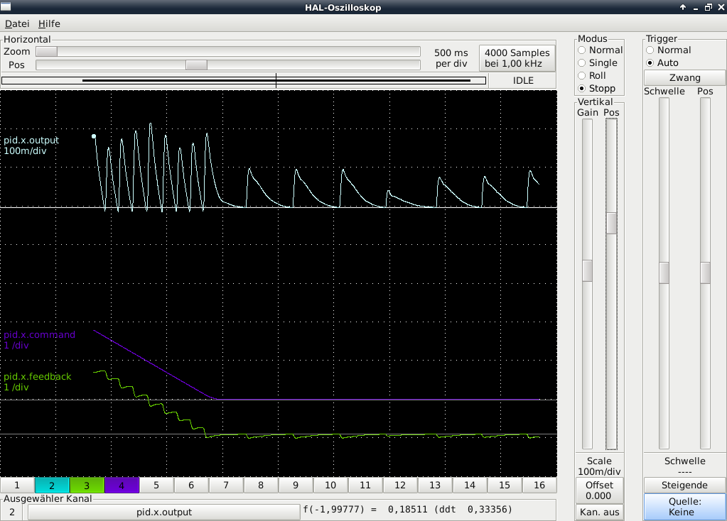
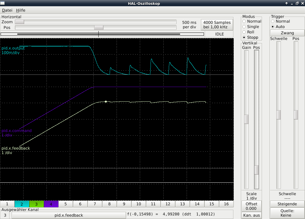
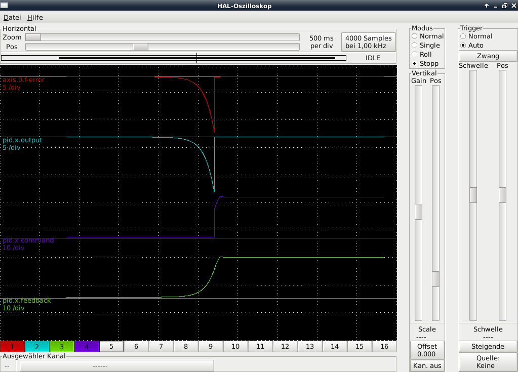
Halscope plots of the PID output value, commanded and feedback position would be helpful
Also posting the HAL and INI files may help
(that is, is this possibly a drive issue?)
Can you send any output voltage open loop (via setp) (try +5 and -5)
(that is is this a hardware interface problem)
Does the encoder read accurately?
A 10V output with a P gain of 1.5 means an error of 6.66 mm (assuming mm)
is this much error really present?
(In addition I should almost always be 0 when doing initial tuning )
Halscope plots of the PID output value, commanded and feedback position would be helpful
Also posting the HAL and INI files may help
Please Log in or Create an account to join the conversation.
08 Nov 2016 14:28 - 08 Nov 2016 14:31 #82587
by Chre9
Replied by Chre9 on topic PID Setting for drifting axis
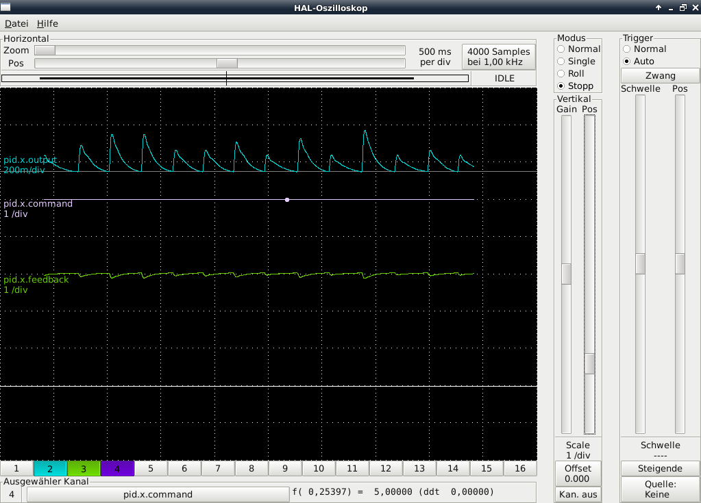
We just recorded the PID output value, commanded and feedback position of the x-axis with halscope while moving in each direction and staying in the same position. First with P=1,5 and I=0,75:
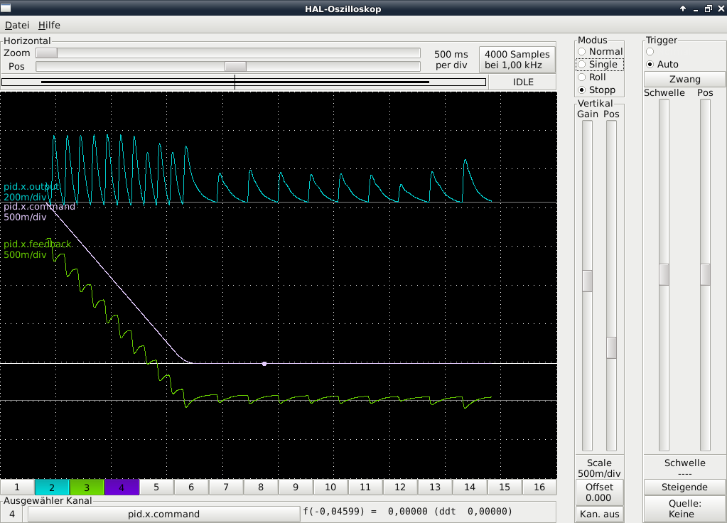
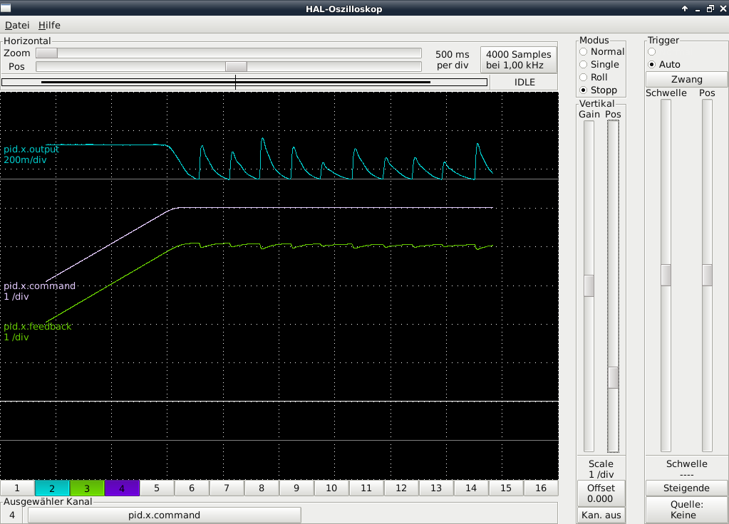
And with P=1 and I=0:
The y and z axes show the same behaviour.
And with P=1 and I=0:
The y and z axes show the same behaviour.
Last edit: 08 Nov 2016 14:31 by Chre9.
Please Log in or Create an account to join the conversation.
08 Nov 2016 14:33 #82588
by Chre9
Replied by Chre9 on topic PID Setting for drifting axis
Here you can find the .ini and .hal document:
We already fixed one of the encoders and they all work properly. Furthermore we have been testing the axis with an external power supply and they move smoothly this way.
We already fixed one of the encoders and they all work properly. Furthermore we have been testing the axis with an external power supply and they move smoothly this way.
Please Log in or Create an account to join the conversation.
08 Nov 2016 14:41 - 08 Nov 2016 19:23 #82589
by PCW
Wrong PWM output type
So what's happening is this:
The 7I48 is designed for UP/DOWN PWM mode (output type 2)
where positive outputs are generated by a PWM signals on the UP pin
and negative outputs are generated by PWM signals on the DOWN pin
the absolute analog voltage in either case is proportional to the PWM duty cycle
If you instead run the 7I48 with the PWM generator in PWM / DIR mode (output mode 1)
it works fine in the direction that the direction pin is 0, but you get a immediate full scale
output (10V) when the PID output sign changes making the direction pin high
Replied by PCW on topic PID Setting for drifting axis
setp hm2_5i20.0.pwmgen.04.output-type 1
Wrong PWM output type
So what's happening is this:
The 7I48 is designed for UP/DOWN PWM mode (output type 2)
where positive outputs are generated by a PWM signals on the UP pin
and negative outputs are generated by PWM signals on the DOWN pin
the absolute analog voltage in either case is proportional to the PWM duty cycle
If you instead run the 7I48 with the PWM generator in PWM / DIR mode (output mode 1)
it works fine in the direction that the direction pin is 0, but you get a immediate full scale
output (10V) when the PID output sign changes making the direction pin high
Last edit: 08 Nov 2016 19:23 by PCW. Reason: clarify
Please Log in or Create an account to join the conversation.
10 Nov 2016 18:48 #82684
by Chre9
Replied by Chre9 on topic PID Setting for drifting axis
Thanks for the explanation.
We changed output mode to 2.
Now, when we start the machine the axis starts to accellerate to a high velocity until a joint following error appears.
Is it possible, that it tries to home the axis?
We changed output mode to 2.
Now, when we start the machine the axis starts to accellerate to a high velocity until a joint following error appears.
Is it possible, that it tries to home the axis?
Please Log in or Create an account to join the conversation.
10 Nov 2016 18:56 - 10 Nov 2016 18:57 #82685
by PCW
Replied by PCW on topic PID Setting for drifting axis
That's expected (it means the loop feedback is positive instead of negative)
The fix is to reverse the PWM output scale, that is change:
OUTPUT_SCALE = 10.0
to:
OUTPUT_SCALE = -10.0
in the per AXIS sections of the .ini file
The fix is to reverse the PWM output scale, that is change:
OUTPUT_SCALE = 10.0
to:
OUTPUT_SCALE = -10.0
in the per AXIS sections of the .ini file
Last edit: 10 Nov 2016 18:57 by PCW. Reason: sectionS
The following user(s) said Thank You: Chre9
Please Log in or Create an account to join the conversation.
Time to create page: 0.386 seconds