Spindle Control 3 Gear Mill (BF30)
29 Jan 2017 09:35 #86889
by abfa9358
Spindle Control 3 Gear Mill (BF30) was created by abfa9358
Hi
I am stuck with best to control my spindle and cant find forum threads that cover my needs.
My machine is configured as follows:
3 gears selected manually.
VFD drive under linuxcnc control, speed ranges (approx) 150 to 600, 300 to 1100 and 500 to 3000.
720 ppr quadrature encoder with index.
"Requirements"
1. when in range cmd rpm = spindle rpm (within a few %)
2. manual gear selection
3. if spindle cant achieved commanded rpm machine waits + "error" led in Glade pyvcp panel (I know how to do this justed added for completeness)
Options Looked at
1. Lincurve - seems more appropriate for fixed rpm motor and fixed ratio transmission.
2. Detect gear with proximity sensors and MUX parameters of transfer function for each gear
3. PID - a whole evening spent with spindle not turning, accelerating instantly to 3000rpm etc.
Other ideas
1. Could I use the start rpm to detect and "lock" HAL to a gear then set the MUX for the scaling parameters?
Any thoughts, comments etc. will gratefully received.
Regards
Andy
Please Log in or Create an account to join the conversation.

29 Jan 2017 10:17 #86891
by rodw
Replied by rodw on topic Spindle Control 3 Gear Mill (BF30)
I might not have all the answers, but conceptually, this is very similar to scale selection on a MPG using a 4 position binary switch and MUX4. You would end up with off, gear 1, gear 2 and gear 3 using just 2 input pins.
Using mult2 would let you scale the RPM and if you have to change the gear lever manually, why not flick a switch at the same time? LCNC should be able to work out if the switch is in the wrong position for the commanded RPM on resume and wait until you get it right.
Using mult2 would let you scale the RPM and if you have to change the gear lever manually, why not flick a switch at the same time? LCNC should be able to work out if the switch is in the wrong position for the commanded RPM on resume and wait until you get it right.
The following user(s) said Thank You: abfa9358
Please Log in or Create an account to join the conversation.
29 Jan 2017 15:19 #86908
by abfa9358
Replied by abfa9358 on topic Spindle Control 3 Gear Mill (BF30)
Yes this will work, I was wondering if there was a cunning HAL solution that didnt involve me adding proximity sensorsetc. just being lazy I guess ")
Please Log in or Create an account to join the conversation.

31 Jan 2017 01:45 #87027
by andypugh
Replied by andypugh on topic Spindle Control 3 Gear Mill (BF30)
Please Log in or Create an account to join the conversation.
31 Jan 2017 05:29 #87040
by abfa9358
Replied by abfa9358 on topic Spindle Control 3 Gear Mill (BF30)
To be honest I read this a number of times and tried to implemented in HAL but I couldnt work out how to cope with following
1. At turn on the spindle have three finite rpm values i.e the c value in y=mx+c
2. The commanded vs actual rpm ratios are nonlinear across the range of the vfd in each gear
I must missing somthing because your example is analogous to mine i.e. "gear box" + vfd
For now, I have just created 3 radio buttons in my Glade panel - following on from above + a sprinkle of laziness
Please Log in or Create an account to join the conversation.
31 Jan 2017 10:18 #87049
by rodw
Replied by rodw on topic Spindle Control 3 Gear Mill (BF30)
Andy is so clever with this stuff!
I think what he's saying is that you don't need a sensor for the gear lever position. if you can measure the speed of the input shaft and the output shaft, you can then calculate the gear ratio at any given speed. So if you have say a 5:1 ratio gear reduction the ratio will always be 0.2 regardless if the speed is 1 rpm or 1000 rpm when that gear is selected. I have not looked at lincurve but I think becasue he had so many gear settings, he has created a graph using it that if drawn would look like a staircase which then simplifies the conversion of the ratio on one axis to your gears 1,2 & 3 on the other axis. Each gear (1,2,3) would be centred on the middle of a horizontal stair tread so that any inaccuracies in the sensors are catered for in a +/- range from the calculated ratio. In his case, this was probably more important as he was synthesising the speed on one of the shafts.
Very clever Andy!
Please Log in or Create an account to join the conversation.
31 Jan 2017 18:35 #87082
by abfa9358
Replied by abfa9358 on topic Spindle Control 3 Gear Mill (BF30)
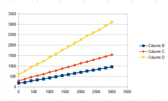
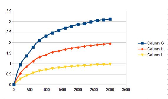
Yes I understand the principle and things would be simple if I was monitoring the motor shaft rpm and the spindle. As Andy points out this is difficult on a hobby mill and so the input monitoring point is the commanded rpm. This leads in my case to a set of very nonlinear curves. First attached plot is commanded vs actual spindle rpm for each gear, second plot is commanded vs (commanded/spindle).
As you can see, the initial response is very nonlinear and i am not sure how to define the staircase such that the feedback loop converges on the correct gear setting.
As you can see, the initial response is very nonlinear and i am not sure how to define the staircase such that the feedback loop converges on the correct gear setting.
Please Log in or Create an account to join the conversation.
31 Jan 2017 18:54 #87084
by andypugh
Replied by andypugh on topic Spindle Control 3 Gear Mill (BF30)
The separation seems reasonable above 750 rpm, and you probably don't want to run the motor at 12Hz anyway.
So it might work.
So it might work.
Please Log in or Create an account to join the conversation.
02 Feb 2017 04:57 #87143
by abfa9358
Replied by abfa9358 on topic Spindle Control 3 Gear Mill (BF30)
thanks Andy.
how about this as a concept,
1. cmd rpm => scale0 => pwm.value (outbound signal, gain / offset set by 4. and 5 below)
2. spindle rpm => scale1.in, scale2.in, scale3.in (inbound signals, scales set with inverse transfer function for each gear i.e. predict cmd rpm
3. scale1.out, 2.out, 3.out + cmd rpm => near1.in, near2.in, near3.in
4. near1.out, 2.out, 3.out => mux4.0 => scale0.gain
5. near1.out, 2.out, 3.out => mux4.1 => scale0.offset
ill try both approaches as time permits
Please Log in or Create an account to join the conversation.
Time to create page: 0.125 seconds