retrofit Bridgeport Prototrak Plus

19 May 2016 22:28 #74867
by andypugh
Replied by andypugh on topic retrofit Bridgeport Prototrak Plus
For the avoidance of doubt, on the Mesa cards Pin1 on each connector block has a square solder pad on the reverse,
The following user(s) said Thank You: new2linux
Please Log in or Create an account to join the conversation.
21 May 2016 17:47 - 21 May 2016 17:52 #74916
by new2linux
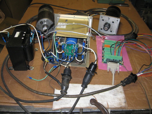
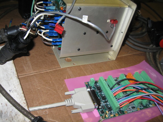
Attached is the assembly as of now, attached to the computer with pre-installed installed Linux on a dedicated drive. I have not powered up yet but am wondering if there is more to to the wiring. The pic does not show the computer it is on a cart so its movable. For a fresh, 1st time start up of the Linux OP system is there suggested reading or words of wisdom that shroud be honored?
As you see in pic 800_1. (the middle pic) the small red plug on the side of the aluminum box with the small jumper (this is the "x" axes), should I leave these plugged in? The other end of the "y" axes is showed hanging underneath and to the left.
Replied by new2linux on topic retrofit Bridgeport Prototrak Plus
Attached is the assembly as of now, attached to the computer with pre-installed installed Linux on a dedicated drive. I have not powered up yet but am wondering if there is more to to the wiring. The pic does not show the computer it is on a cart so its movable. For a fresh, 1st time start up of the Linux OP system is there suggested reading or words of wisdom that shroud be honored?
As you see in pic 800_1. (the middle pic) the small red plug on the side of the aluminum box with the small jumper (this is the "x" axes), should I leave these plugged in? The other end of the "y" axes is showed hanging underneath and to the left.
Last edit: 21 May 2016 17:52 by new2linux.
Please Log in or Create an account to join the conversation.
- Todd Zuercher
-

- Offline
- Platinum Member
-

Less
More
- Posts: 4962
- Thank you received: 1369
22 May 2016 01:16 #74930
by Todd Zuercher
Replied by Todd Zuercher on topic retrofit Bridgeport Prototrak Plus
Yes the wire with the red plug connected to the amp is very important. It carries the analog signal that controls the amps, and it needs to be connected to the 7i77. The jumper wire may well be an amp enable, and might be worthwhile connecting as well.
The following user(s) said Thank You: new2linux
Please Log in or Create an account to join the conversation.
22 May 2016 13:02 #74944
by new2linux
Replied by new2linux on topic retrofit Bridgeport Prototrak Plus
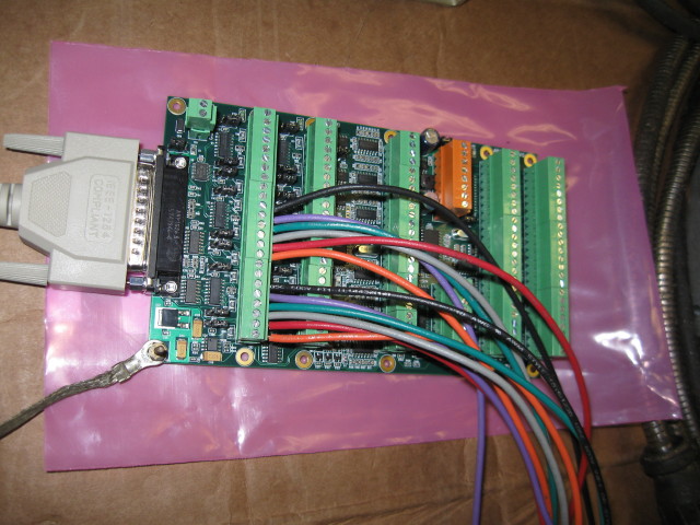
I have found sockets like this one from a computer but only 5 positions, there are 6 contacts on the power amplifier.
Should I be looking for a 6 contact plugs to match the amp on one end and only wire on the other, as to go to the 7i77?
Thanks
Should I be looking for a 6 contact plugs to match the amp on one end and only wire on the other, as to go to the 7i77?
Thanks
Please Log in or Create an account to join the conversation.
22 May 2016 13:23 - 22 May 2016 13:23 #74947
by andypugh
Replied by andypugh on topic retrofit Bridgeport Prototrak Plus
www.mouser.co.uk/Connectors/Headers-Wire...&Keyword=M20&FS=True
Note that you need to buy the terminals separately.
Note that you need to buy the terminals separately.
Last edit: 22 May 2016 13:23 by andypugh.
The following user(s) said Thank You: new2linux
Please Log in or Create an account to join the conversation.
22 May 2016 17:20 #74955
by new2linux
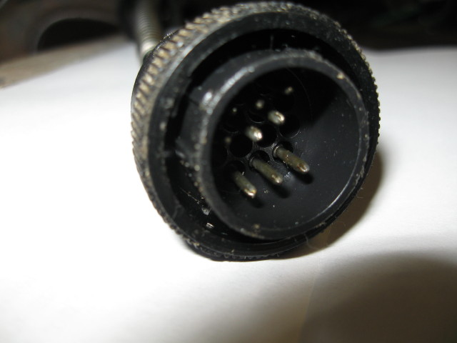
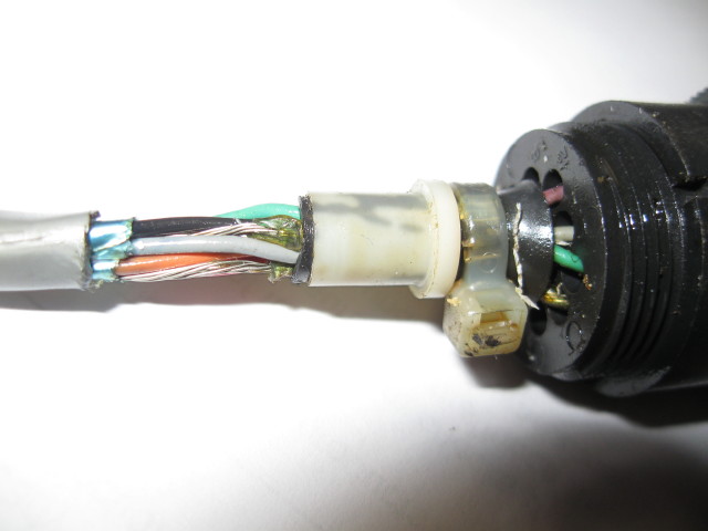
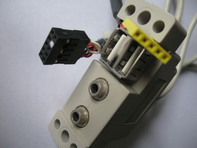
The bottom pic is the cable from the encoder on the drive with the plug disassembled showing 3 sets of bare wires that are connected to the 3 pins in the center of the top pic (this is not the best pic, look carefully the top row you just see the very ends of the pins). In the mating half of plug there is nothing going to the 7i77. After reading the 7i77 man on page 14 at the top talks about the twisted pair (this is cut and paste from the manual)
ANALOG SERVO DRIVE INTERFACE
The 7I77 provides six channels of +-10V analog servo interface on connector TB5.
Minimum load resistance is 2K Ohms. Normally analog servo drives use differential inputs
to avoid ground loops. Suggested wiring is shielded twisted pair with7I77 AOUTN to drive
AIN+, 7I77 GNDN (adjacent to AOUTN) to drive AIN- as the twisted pair and 7I77 GNDN
connected to the shield at the 7I77 end only. The drives common or GND signal should be
connected to the 7I77 power GND with a separate wire.
Each require a wire to the case, or use jumper to connect all together at plug area with single wire to ground at case?
Todd, The manual on page 17 says:
ANALOG INPUTS
All field input pins are capable of reading the input voltage. These are not highly
accurate or high resolution but can be useful for things like potentiometer inputs. Input
resolution is 8 bits and input full scale value is 36.3V. Accuracy is +-5%
Software process data modes 1 and 2 allow reading the analog voltage on inputs
0 through 3, in addition to the 32 digital bit inputs.
Is this is the location for these inputs? Referencing the red plugs and there wires.
Thanks
Replied by new2linux on topic retrofit Bridgeport Prototrak Plus
The bottom pic is the cable from the encoder on the drive with the plug disassembled showing 3 sets of bare wires that are connected to the 3 pins in the center of the top pic (this is not the best pic, look carefully the top row you just see the very ends of the pins). In the mating half of plug there is nothing going to the 7i77. After reading the 7i77 man on page 14 at the top talks about the twisted pair (this is cut and paste from the manual)
ANALOG SERVO DRIVE INTERFACE
The 7I77 provides six channels of +-10V analog servo interface on connector TB5.
Minimum load resistance is 2K Ohms. Normally analog servo drives use differential inputs
to avoid ground loops. Suggested wiring is shielded twisted pair with7I77 AOUTN to drive
AIN+, 7I77 GNDN (adjacent to AOUTN) to drive AIN- as the twisted pair and 7I77 GNDN
connected to the shield at the 7I77 end only. The drives common or GND signal should be
connected to the 7I77 power GND with a separate wire.
Each require a wire to the case, or use jumper to connect all together at plug area with single wire to ground at case?
Todd, The manual on page 17 says:
ANALOG INPUTS
All field input pins are capable of reading the input voltage. These are not highly
accurate or high resolution but can be useful for things like potentiometer inputs. Input
resolution is 8 bits and input full scale value is 36.3V. Accuracy is +-5%
Software process data modes 1 and 2 allow reading the analog voltage on inputs
0 through 3, in addition to the 32 digital bit inputs.
Is this is the location for these inputs? Referencing the red plugs and there wires.
Thanks
Please Log in or Create an account to join the conversation.
- Todd Zuercher
-
- Offline
- Platinum Member
-
Less
More
- Posts: 4962
- Thank you received: 1369
22 May 2016 18:12 #74956
by Todd Zuercher
Replied by Todd Zuercher on topic retrofit Bridgeport Prototrak Plus
I'm not sure it matters much. I think the old control only is using 2 of the pins. Something like the 1st and 3rd pin. There is a wire on the 2nd pin, but I couldn't see any traces on the breakout board going to it. You could try to buy a plug that coverss all the connectors, or you could get smaller, individual ones that plug separately, or you could try tor reuse the old connectors.
Personally, I think I'd have just left everything in the old cabinet alone, plugged an old parallel port cable into the db25 plug whacked off the other end and connected those wires to the 7i77 rather than messing with trying to find all those different odball connectors,
Personally, I think I'd have just left everything in the old cabinet alone, plugged an old parallel port cable into the db25 plug whacked off the other end and connected those wires to the 7i77 rather than messing with trying to find all those different odball connectors,
The following user(s) said Thank You: new2linux
Please Log in or Create an account to join the conversation.
23 May 2016 20:14 - 23 May 2016 20:15 #75004
by new2linux
Replied by new2linux on topic retrofit Bridgeport Prototrak Plus
I asked Todd the following:
Question: I have read the manual for the 7i77 and 5i55 cards and it talks about the type of signal it is expecting and where to place that wire, but where I am lost on what wire goes where.
Answer: For your analog control signals you would connect wires from your P1-P2 and P3-P4 to the 7i77's TB5 pins 3&4 and 7&8 (it may or may not matter which one goes where)
Question: This is from an earlier email to me from you, what does "GPIO" mean?
Answer: The acronym GPIO stands for General Purpose Input Output.
More from Todd: The 7i77 needs to be powered by 2 DC power sources, a 5v low voltage one and a higher voltage one (8-32v) that powers the GPIO part of the card. The 5v part can come from the computer via the plug between the 7i77 and the 5i25 (if the jumpers on both cards are configured for this) The "field power" 8-32v DC is used for things like your limit-switches and such most people use 12 or 24v, and you can use a wall wart to supply this.
The old control would have used a relay or contactor to turn the power to the servo amps on/off. You could possibly use the servo enable switches on the 7i77 to control that same relay (if power levels are acceptable)
For your analog control signals you would connect wires from your P1-P2 and P3-P4 to the 7i77's TB5 pins 3&4 and 7&8 (it may or may not matter which one goes where)
Your E-stop will likely be a series of relays and or contactors that will be triggered by a gpio output on the 7i77 and also send a signal to a gpio input (so that Linuxcnc stops) when you push the big red button.
Limit switches will connect to gpio inputs
Are you adding the Z axis at this time?
Does your machine have linear slide encoders or glass scales in addition to the encoders on the motors? And do you intend to use them?
Their feedback can be added, but it does add another layer of complexity to configuring the machine.
many thanks!
Last edit: 23 May 2016 20:15 by new2linux.
Please Log in or Create an account to join the conversation.
24 May 2016 12:02 #75035
by andypugh
Replied by andypugh on topic retrofit Bridgeport Prototrak Plus
To explain the wiring, the cable has three individualy screened twisted pairs. Each twisted pair is wrapped in mylar and aluminium and there is a drain wire intended to make contact with the shielding. It is the drain wire that you see as a bare wire, and all three probably connect to a common earth terminal.
Please Log in or Create an account to join the conversation.
24 May 2016 13:00 - 24 May 2016 13:03 #75040
by new2linux
Replied by new2linux on topic retrofit Bridgeport Prototrak Plus
Does the 3 pins need to connect to something on the other half of the plug that goes to the 7i77 or does is the shielding make it go to ground?
Last edit: 24 May 2016 13:03 by new2linux.
Please Log in or Create an account to join the conversation.
Moderators: piasdom
Time to create page: 0.188 seconds