Prototrak Plus Retrofit with Mesa 7i77 & 5i25 cards
10 Mar 2017 17:00 - 10 Mar 2017 17:16 #89345
by new2linux
Replied by new2linux on topic Prototrak Plus Retrofit with Mesa 7i77 & 5i25 cards
Many thanks Dan! The DRV O & DRV 1 is (TB 5) on 7i77 card. I will look again at page 9. Will post pic soon.
many thanks!
Edit: I have read your load suggestion, this is at the large black transformer, the terminals going to the rectifier and amp, place 110v light bulb to 2 of the 3 leads going between rectifier and transformer. Just need to be clear.
many thanks!
Edit: I have read your load suggestion, this is at the large black transformer, the terminals going to the rectifier and amp, place 110v light bulb to 2 of the 3 leads going between rectifier and transformer. Just need to be clear.
Last edit: 10 Mar 2017 17:16 by new2linux. Reason: clearify
Please Log in or Create an account to join the conversation.
10 Mar 2017 17:09 #89347
by new2linux
Replied by new2linux on topic Prototrak Plus Retrofit with Mesa 7i77 & 5i25 cards
Many thanks andypugh! I recall the rectifier having an post that was odd arrangement, I will be looking close and will post pic if it will help. With the power off and discharged capacitor, I will be testing continuity from the rectifier (post in question) to the terminal output of PSB/capacitor assembly, correct.
many, many thanks! (if correct just don't post)
many, many thanks! (if correct just don't post)
Please Log in or Create an account to join the conversation.

10 Mar 2017 17:27 #89350
by lakeweb
Replied by lakeweb on topic Prototrak Plus Retrofit with Mesa 7i77 & 5i25 cards
I can't be sure which terminals are which just from the pic. That is why the light bulb and volt meter. You can be sure you are hooked to a loadable DC output. With a light bulb, if you hook up to anything else, you won't hurt anything. (At least, it is highly unlikely.)
Best, Dan.
Best, Dan.
The following user(s) said Thank You: new2linux
Please Log in or Create an account to join the conversation.
10 Mar 2017 18:01 - 10 Mar 2017 18:02 #89354
by new2linux
Replied by new2linux on topic Prototrak Plus Retrofit with Mesa 7i77 & 5i25 cards
Many thanks Andy and Dan! Here are a few pics, use for reference, because it needs to be correct.
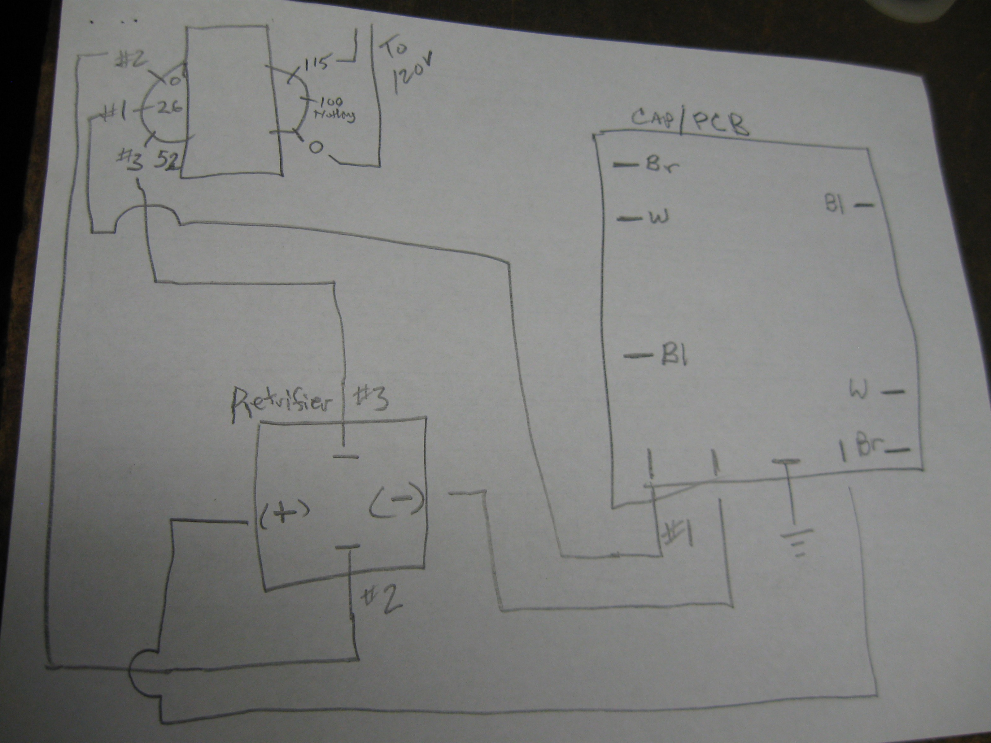 this is a diagram of the leads, if you see the rectifier is marked + on the left & - on right. Also the PSB is enlarged in the diagram, with the Brown=Br; White=W; Blue= Bl. I have taken just best guess for the locations in the pic. The other pic is of the amp with the fan assembly rotated for better view.
Many thanks!
Many thanks!
Last edit: 10 Mar 2017 18:02 by new2linux. Reason: clearify
Please Log in or Create an account to join the conversation.

10 Mar 2017 18:24 #89356
by andypugh
Replied by andypugh on topic Prototrak Plus Retrofit with Mesa 7i77 & 5i25 cards
It seems fairly clear that white is negative.
But as for which of blue or brown is positive, I can't really tell.
What does the multimeter say? Which connects to the + terminal of the capacitor?
But as for which of blue or brown is positive, I can't really tell.
What does the multimeter say? Which connects to the + terminal of the capacitor?
The following user(s) said Thank You: new2linux
Please Log in or Create an account to join the conversation.
10 Mar 2017 18:25 #89357
by new2linux
Replied by new2linux on topic Prototrak Plus Retrofit with Mesa 7i77 & 5i25 cards
Thank you Andy & Dan! To insure this is tested correctly I place 110v light between 1 & 3 measure voltage; 1 & 2 measure voltage; 2 & 3 measure voltage, changing the light as I go to the next set of leads. Will this also answer Andy's question about 80v. I can pull other capacitor out to see back side of PCB if it is better that way.
many thanks!!
many thanks!!
Please Log in or Create an account to join the conversation.
10 Mar 2017 19:10 #89362
by new2linux
Replied by new2linux on topic Prototrak Plus Retrofit with Mesa 7i77 & 5i25 cards
Many many thanks!!
The results form having 110v light in circuit and testing with voltmeter. 1 & 2 on 12v scale needle moved both ways(+ & -) on scale, moved very small amount.
1 & on 12v scale needle moved both ways(+ & -) on scale, moved very small amount.
3 & 2 on 12v scale needle moved both ways(+ & -) on scale, moved the largest amount. The light was on, but dim.
thanks for all your help!!
Please Log in or Create an account to join the conversation.
10 Mar 2017 19:30 #89365
by andypugh
Replied by andypugh on topic Prototrak Plus Retrofit with Mesa 7i77 & 5i25 cards
Why are you using a 12V scale? Aren't these 80V servo drivers?
Something isn't making sense here.
Something isn't making sense here.
Please Log in or Create an account to join the conversation.
10 Mar 2017 19:35 - 10 Mar 2017 19:37 #89367
by new2linux
Replied by new2linux on topic Prototrak Plus Retrofit with Mesa 7i77 & 5i25 cards
Thank you Andy!
The needle moved such a small amount on the 60v that it was hard to decide how much it moved. Even on 12v scale it was very small amount. This measurement is at the transformer not the PCB or capacitor.
thanks!
The needle moved such a small amount on the 60v that it was hard to decide how much it moved. Even on 12v scale it was very small amount. This measurement is at the transformer not the PCB or capacitor.
thanks!
Last edit: 10 Mar 2017 19:37 by new2linux. Reason: spelling
Please Log in or Create an account to join the conversation.
10 Mar 2017 19:54 #89371
by andypugh
Why?
Also, you would need to use the AC setting at that point. (And DC on the other side of the rectifier)
Replied by andypugh on topic Prototrak Plus Retrofit with Mesa 7i77 & 5i25 cards
This measurement is at the transformer not the PCB or capacitor.
Why?
Also, you would need to use the AC setting at that point. (And DC on the other side of the rectifier)
Please Log in or Create an account to join the conversation.
Moderators: piasdom
Time to create page: 0.169 seconds