No Input Signals
I'm new to this forum and recently began building my own cnc-mill. I have a PC connected to a quality chinese breakoutboard (the 5-axis controller things which are to find on various sites). The motor setup works like a charm through stepconf wizard but the input signals seem to be missing. I have inductivity sensors set-up as limit switches and home switches. Because there is a power requirement for these inductivity switches I connected them to a power supply with 24 VDC. I have a common ground with power supply (-24V) and breakout board. The ground is shared with inductivity switches. As I thought there would be a potential of 24V between open switch pin and ground on the break out board. But nothing happens. Now I've already looked for that specific problem and found a promising solution mentioned here: linuxcnc.org/index.php/english/forum/18-...rport?start=10#58885
. My question: Is it safe to do this wiring to +5VDC computer power if I'm a) powering the board with the USB port and b) have a 24V potential between the input pins and gnd? Should I alter resistance values or solder as seen in mentioned picture?
The inductivity sensors definitely work (I troubleshot them) and also the analogous emergency kill switch (Connecting gnd with pin 10) does not work in any way.
Thank you very much in advance
~Alfongs

Edit: I hope this fits in here because the issue is concerning the parallel port. if not please move this thread to the corresponding subforum.
Please Log in or Create an account to join the conversation.

Are your Proximity switches NPN or PNP type?
On NPN types the output is a switch to ground so inputs need a pullup (this can be to 5V if the inputs only take 5V maximum)
On PNP types the output is a switch to V+ (24V in your case) so inputs need a pulldown and need to accept a 24V input without damage
The pullups added to the breakout board you referenced are on the parallel port side, not the machine side of the breakout
Please Log in or Create an account to join the conversation.
")
Please Log in or Create an account to join the conversation.
I don't know what could be wrong with this, but maybe my installation is faulty? I downloaded the ISO image with a debian OS on it. I've heard there is also a Ubuntu version of this system. Maybe it will suffice to install a new OS?
Please Log in or Create an account to join the conversation.
I have a PC connected to a quality chinese breakoutboard (the 5-axis controller things which are to find on various sites).
Something of a contradiction in terms, 'quality' and 'Chinese'. Is it a BOB or actually a TB6600 type driver?
Without knowing what it is, very hard to assist.
I don't know what could be wrong with this, but maybe my installation is faulty? I downloaded the ISO image with a debian OS on it. I've heard there is also a Ubuntu version of this system. Maybe it will suffice to install a new OS?
If that were the case, no one using the Wheezy image would be able to get it to work.
If you have not already blown everything by connecting 24v to 5v (or even 3.3v) TTL circuits, the problem will be your wiring or your BOB or the connections between.
Please attach your ini and hal files and tell us what you are connecting to.
regards
Please Log in or Create an account to join the conversation.
") . I have this bob attached to 3 motor-drivers.
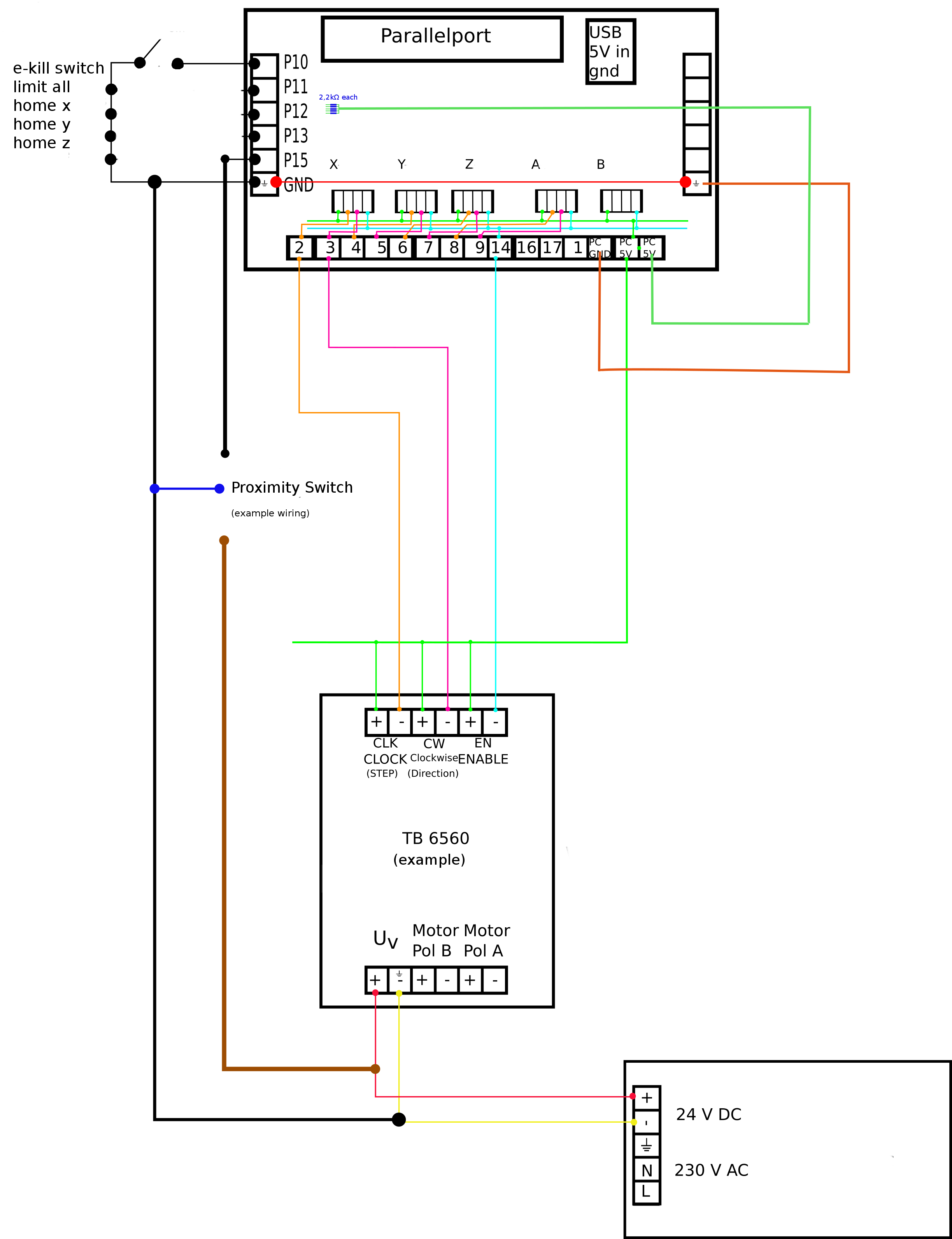
. I have this bob attached to 3 motor-drivers.I also got a wiring diagram (see attachment).
Where do I find my .ini and .hal files?
The proximity switches are NPN NO
Please Log in or Create an account to join the conversation.

They are NPN proximity switches, so I'm going for the solution mentioned above.
It isn't entirely clear what you have done, but the Proximity switches are likely to need 24V (or at least 12V) to work.
So, you wire 24V to the Prox V+, wire the Prox 0V to the common BoB and 24V gnd. (no way to keep separate GND with this setup) then wire the prox output to the BoB input terminal.
You then need a connection (1k or so) from the BoB input terminal to +5V.
Rather than have the complexity of LinuxCNC to confuse matters, get the inputs working with the parallel port tester first:
wiki.linuxcnc.org/cgi-bin/wiki.pl?Parallel_Port_Tester
Please Log in or Create an account to join the conversation.
It isn't entirely clear what you have done
Maybe the drawing is unclear, I try to explain. The switches next to the pins (10-15) are except from the emergency switch just a placeholder (due to limited space on this drawing). The real cabling is shown below (with the caption Proximity sensor).
They have a range from 6V-36V. I'm downloading this tester and then hope to see the problem.It isn't entirely clear what you have done, but the Proximity switches are likely to need 24V (or at least 12V) to work.
no way to keep separate GND with this setup
yes, my intention is to have one common gnd for all.

Please Log in or Create an account to join the conversation.
Where do I find my .ini and .hal files?
/home/<user-name>/linuxcnc/configs/<config-name>
Please Log in or Create an account to join the conversation.
: Still no Input signals, so I used a wire and connected pin 25 (gnd) sequentially with the input pins 10, 11, 12, 13, 15. And voila, it shows up in the programme!
That means something of my wiring is bad or the bob is not okay.
I also connected the pc gnd to the 24V power supply gnd.
See attachment for most recent version of my connections
Please Log in or Create an account to join the conversation.