G33.1 right hand tapping weird behavior H E L P !
18 Feb 2015 18:04 #56071
by tkamsker
G33.1 right hand tapping weird behavior H E L P ! was created by tkamsker
Hi,
i am almost finished with my bridgeport retrofit now at training stage i found out that G33.1 (because i normally don't use it ) doesn't behave as it should.
i have also prepared an python drill script generator which i donate when we solve that") -
-
So i go to lets say g0 x0 y0 z0.5
S200 M3
G33.1 Z-3 K1.5
i would expect that it does go down to Z-3 in the needed speed to achieve 1.5 per revolution
so far so good (i looks that i have a glitch from motor to spindle it is a 1:2 ratio but ,.. )
so i use a bigger number in K to achieve the ratio )
but when the system reaches Z-3 it reverses the spindle also ok
but then it proceeds i stopped it then at Z-30
so has anyone seen that behavior and how can i check what i probably have done wrong ?
or if someone has an Working G84 script which i can remap would also help a lot
i use now the latest live cd and do updates
so any hint welcome
thx
thomas kamsker
i am almost finished with my bridgeport retrofit now at training stage i found out that G33.1 (because i normally don't use it ) doesn't behave as it should.
i have also prepared an python drill script generator which i donate when we solve that
-So i go to lets say g0 x0 y0 z0.5
S200 M3
G33.1 Z-3 K1.5
i would expect that it does go down to Z-3 in the needed speed to achieve 1.5 per revolution
so far so good (i looks that i have a glitch from motor to spindle it is a 1:2 ratio but ,.. )
so i use a bigger number in K to achieve the ratio )
but when the system reaches Z-3 it reverses the spindle also ok
but then it proceeds i stopped it then at Z-30
so has anyone seen that behavior and how can i check what i probably have done wrong ?
or if someone has an Working G84 script which i can remap would also help a lot
i use now the latest live cd and do updates
so any hint welcome
thx
thomas kamsker
Please Log in or Create an account to join the conversation.

18 Feb 2015 21:58 #56075
by andypugh
Replied by andypugh on topic G33.1 right hand tapping weird behavior H E L P !
but when the system reaches Z-3 it reverses the spindle also ok
but then it proceeds i stopped it then at Z-30 /quote]
Does your spindle encoder definitely count both up and down? It sounds to me like you might be in counter-mode and the system thinks that the spindle is still moving in the same direction.
The following user(s) said Thank You: tkamsker
Please Log in or Create an account to join the conversation.
19 Feb 2015 00:45 #56083
by tkamsker
Replied by tkamsker on topic G33.1 right hand tapping weird behavior H E L P !
Hi andy,
Thank you for the fast answer
i think the encoder can not count backwards because i only have Z and A signal on the same pin
i thought because of the reverse spindle it should "know" that it is backwards.
Is there any known configuration which makes this possible or do i have to mount an B signal 90° from the A signal ?
this is something we could manage would that help ?
i then would have A and Index on one signal and B on an 2nd 90° apart
thomas
Please Log in or Create an account to join the conversation.
19 Feb 2015 00:59 #56085
by andypugh
Just because a spindle reversal has been requested does not mean that the spindle has actually changed direction.
I am afraid that there probably is no alternative to adding a second sensor.
It doesn't have to be at 90 degrees, 360+90 or 720+90 etc all work too.
Replied by andypugh on topic G33.1 right hand tapping weird behavior H E L P !
i thought because of the reverse spindle it should "know" that it is backwards.
Is there any known configuration which makes this possible or do i have to mount an B signal 90° from the A signal ?
Just because a spindle reversal has been requested does not mean that the spindle has actually changed direction.
I am afraid that there probably is no alternative to adding a second sensor.
It doesn't have to be at 90 degrees, 360+90 or 720+90 etc all work too.
The following user(s) said Thank You: tkamsker
Please Log in or Create an account to join the conversation.
11 Mar 2015 23:19 #56699
by tkamsker
Replied by tkamsker on topic G33.1 right hand tapping weird behavior H E L P !
Hi andy
i now build an 2nd Probe to my config and can get some better insights
My question which values does the 33 command take in consideration ?
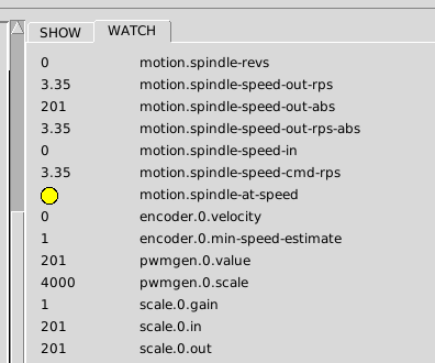
This is an example where i have 201 as RPM and 3,35 as Rev/Sek
And when i turn the direction i is negative
Is that correct ?
Is there an example to work from ?
thx
thomas
i now build an 2nd Probe to my config and can get some better insights
My question which values does the 33 command take in consideration ?
This is an example where i have 201 as RPM and 3,35 as Rev/Sek
And when i turn the direction i is negative
Is that correct ?
Is there an example to work from ?
thx
thomas
Please Log in or Create an account to join the conversation.
11 Mar 2015 23:56 #56704
by andypugh
G33 uses the value of motion.spindle-revs (revolutions, not rpm)
You need to set up the encoder scale so that one rotation clockwise of the spindle gives an increase of exactly 1.0 in motion.spindle-revs and one rotation anticlockwise makes it _reduce_ by exactly 1.0.
Replied by andypugh on topic G33.1 right hand tapping weird behavior H E L P !
My question which values does the 33 command take in consideration ?
G33 uses the value of motion.spindle-revs (revolutions, not rpm)
You need to set up the encoder scale so that one rotation clockwise of the spindle gives an increase of exactly 1.0 in motion.spindle-revs and one rotation anticlockwise makes it _reduce_ by exactly 1.0.
The following user(s) said Thank You: tkamsker
Please Log in or Create an account to join the conversation.
15 Mar 2015 01:56 #56820
by tkamsker
Replied by tkamsker on topic G33.1 right hand tapping weird behavior H E L P !
Hi,
I have an question
I have switched of count of course
have connected A and Z and B is extra so one Revolution of the spindle brings
A and Z
then B
and next revolution the same
And i think that brings me in trouble ,..
I can get Speed rps rpm fine but then revs is 0 -1 or 1
so do i have to attach an encoder which gives AB AB AB AB and so on and only 1 Z per revolution ?
It seems they revs start after 2nd revolution
When i switch counter on and use A and Z (z then on former B ) to have an 90° offset i get everything
but revs keep on counting (when i do G33.1 it starts nice then reverses the spindle but ,... )
So if anybody has some experience with tha minimized setup it would be nice
The bridgeport has done ist somehow by one Pin anyway ,..
but that is another story
thx
thomas
Please Log in or Create an account to join the conversation.

15 Mar 2015 06:56 - 15 Mar 2015 06:56 #56828
by PCW
Replied by PCW on topic G33.1 right hand tapping weird behavior H E L P !
Rigid tapping requires a full A/B/IDX encoder, in addition it needs one with fairly good resolution
in order to accurately "gear" the Z axis to the spindle rotation. One pin is fine for getting
spindle velocity, no so fine for determining exactly when reversal occurs
in order to accurately "gear" the Z axis to the spindle rotation. One pin is fine for getting
spindle velocity, no so fine for determining exactly when reversal occurs
Last edit: 15 Mar 2015 06:56 by PCW.
The following user(s) said Thank You: tkamsker
Please Log in or Create an account to join the conversation.
15 Mar 2015 15:59 #56833
by tkamsker
Replied by tkamsker on topic G33.1 right hand tapping weird behavior H E L P !
Hi PCW ,
thank you for you answer i hoped that i can do it without big changes on the bridgeport
my idea was (because on the original
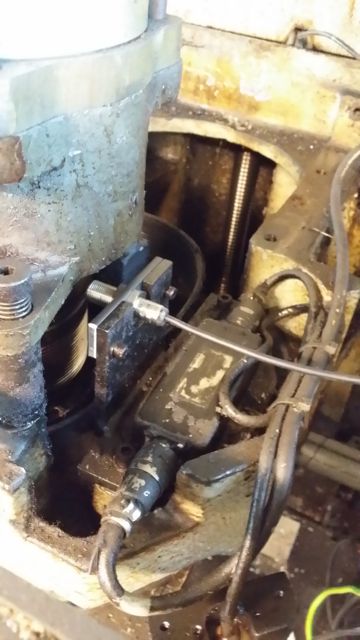 here my adaption ) to use only one "ping"
i now learned that this is not enough
So Plan "B" i build an test on my mill
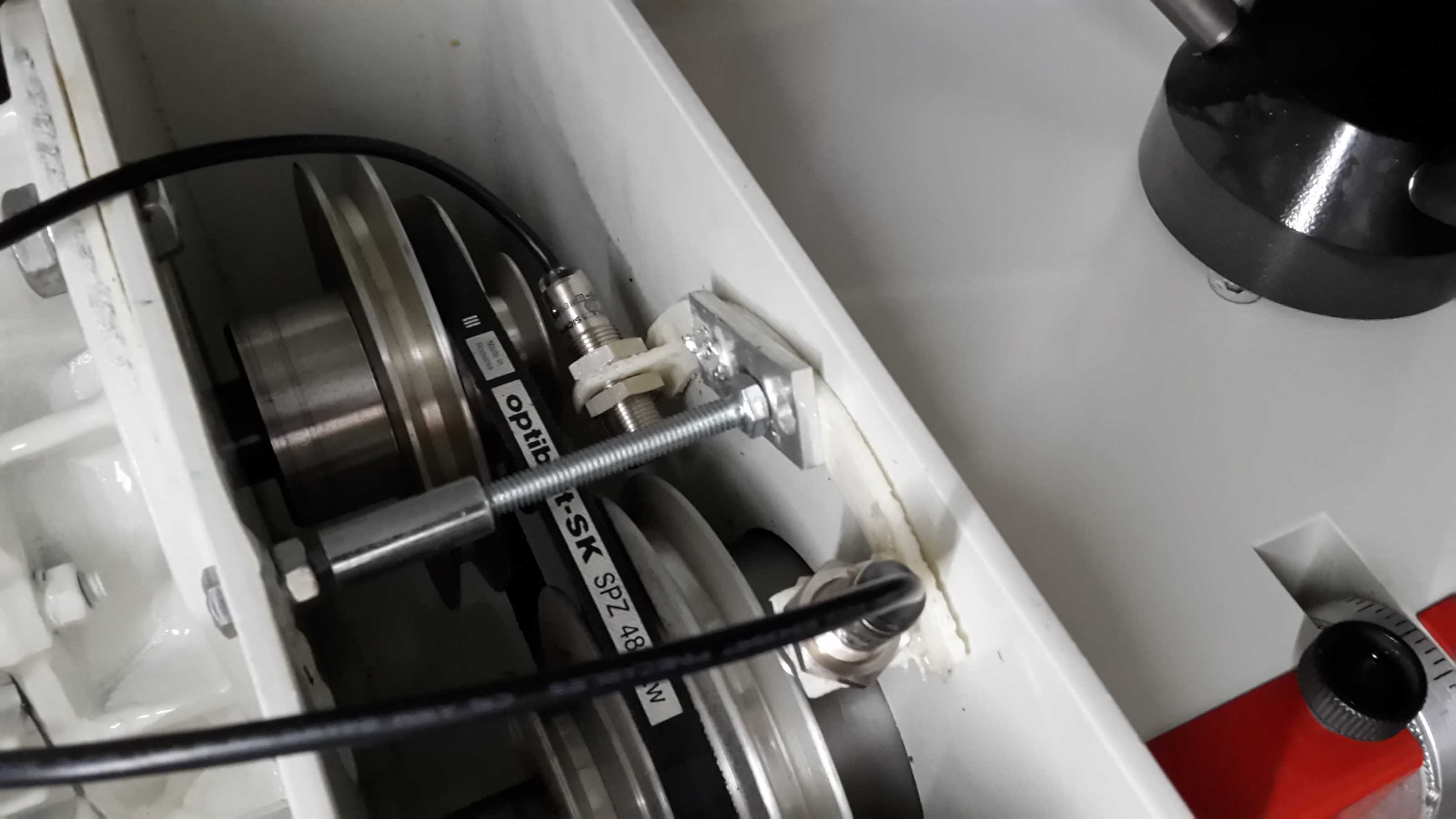 where 2 "Probes" are 90° separated and only 1 steel plate is doing the signal so i hoped to get an A/ B Signal (which i do ) which gives me perfect speed .
but revs are not counted !!! i denn put the index signal to A and later to b signal then the revs never get bigger than 1 or -1
So my conclusion would be to put more metal plates (just for test ) on the spindle to get lets say 4 a/b per revolution and i add an longer metal plate and mount a 3rd "probe" to get the index signal
this would lead to an poor mans encoder ,..
so if someone had done ist similar i would go that route because i have everything at hand (but time)
or if you say encoder i have some AMT 101 Encoders on stock ( www.digikey.at/product-detail/en/AMT102-V/102-1307-ND/827015 ) but the mount on the Bridgeport will be very complicated ( on my lathe i am on the way to do that but that is next task )
So if someone can lead me in the right direction this would help me big times
last resort would be to go the Encoder route
thanx
thomas kamsker
thank you for you answer i hoped that i can do it without big changes on the bridgeport
my idea was (because on the original
i now learned that this is not enough
So Plan "B" i build an test on my mill
but revs are not counted !!! i denn put the index signal to A and later to b signal then the revs never get bigger than 1 or -1
So my conclusion would be to put more metal plates (just for test ) on the spindle to get lets say 4 a/b per revolution and i add an longer metal plate and mount a 3rd "probe" to get the index signal
this would lead to an poor mans encoder ,..
so if someone had done ist similar i would go that route because i have everything at hand (but time)
or if you say encoder i have some AMT 101 Encoders on stock ( www.digikey.at/product-detail/en/AMT102-V/102-1307-ND/827015 ) but the mount on the Bridgeport will be very complicated ( on my lathe i am on the way to do that but that is next task )
So if someone can lead me in the right direction this would help me big times
last resort would be to go the Encoder route
thanx
thomas kamsker
Please Log in or Create an account to join the conversation.
15 Mar 2015 16:37 #56834
by andypugh
You probably want more than 4 pulses. Home-made encoders normally have 50+ slots and commercial ones have 1000+
Do you know what the response time of you sensors is? At high speeds they may start missing edges.
Replied by andypugh on topic G33.1 right hand tapping weird behavior H E L P !
So my conclusion would be to put more metal plates (just for test ) on the spindle to get lets say 4 a/b per revolution and i add an longer metal plate and mount a 3rd "probe" to get the index signal
You probably want more than 4 pulses. Home-made encoders normally have 50+ slots and commercial ones have 1000+
Do you know what the response time of you sensors is? At high speeds they may start missing edges.
The following user(s) said Thank You: tkamsker
Please Log in or Create an account to join the conversation.
Time to create page: 0.243 seconds