Kinematics... again:/

I'm in right?
To better explain what I see and what I understand:
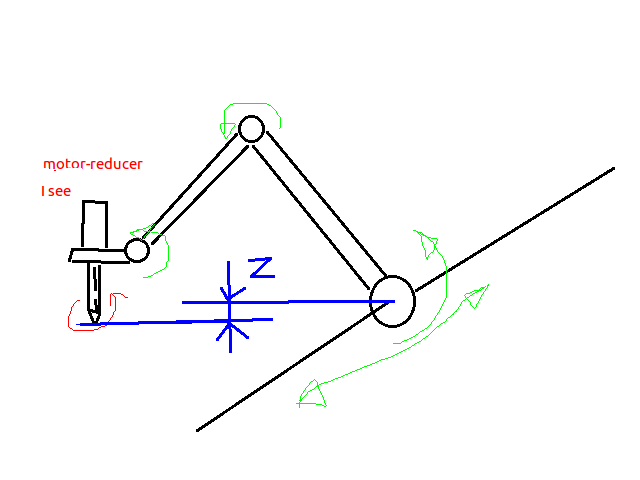
And I belive Andy suggest you the right Z direction and offset ...
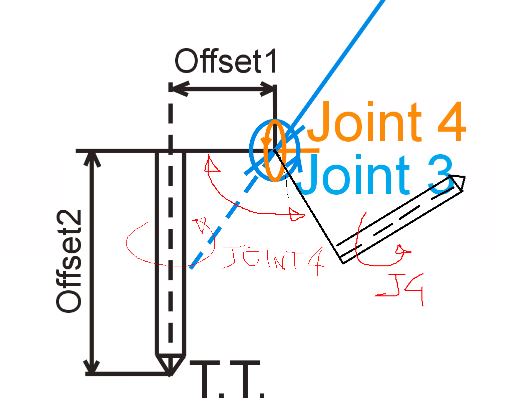
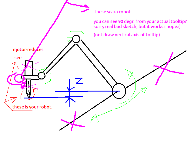
Normally in scarakins tooltip is these (I hope the sketch it's understandable):

so in your case the toltip axis is 90° respect normal case ... (you have only rotary toltip, not linear also, you have only J0 linear).
regards
giorgio
Please Log in or Create an account to join the conversation.
joint[4] = End effector rotates around horizontal axis, that is
perpendicular to previous rotation axis and is parallel to Y axis.
This module assumes there is no offset between joint[3] and joint[4] axes.
...perpendicular to previous rotation axis (which was parallel to cartesian X axis) and parallel to cartesian Y axis. What you have drawn is joint 4 parallel to cartesian Z axis (as long as previous joints keep tool tip normal to cartesian XY plane).
I'm confused:/
Please Log in or Create an account to join the conversation.

Please Log in or Create an account to join the conversation.
I'm not a little genius/magician like AndyPugh, but I hope to understand and explain your problem.
I have the sincere admiration for the work done by Andy (I add this to not be misunderstood).
Regards
giorgio
Please Log in or Create an account to join the conversation.
See attached screenshot.
I want to mount standard milling spindle instead of joint 4 stepper motor (which was used to rotate welding head in original design). And here comes the D3 parameter vs tool lenght offsets.
So it will look like this:
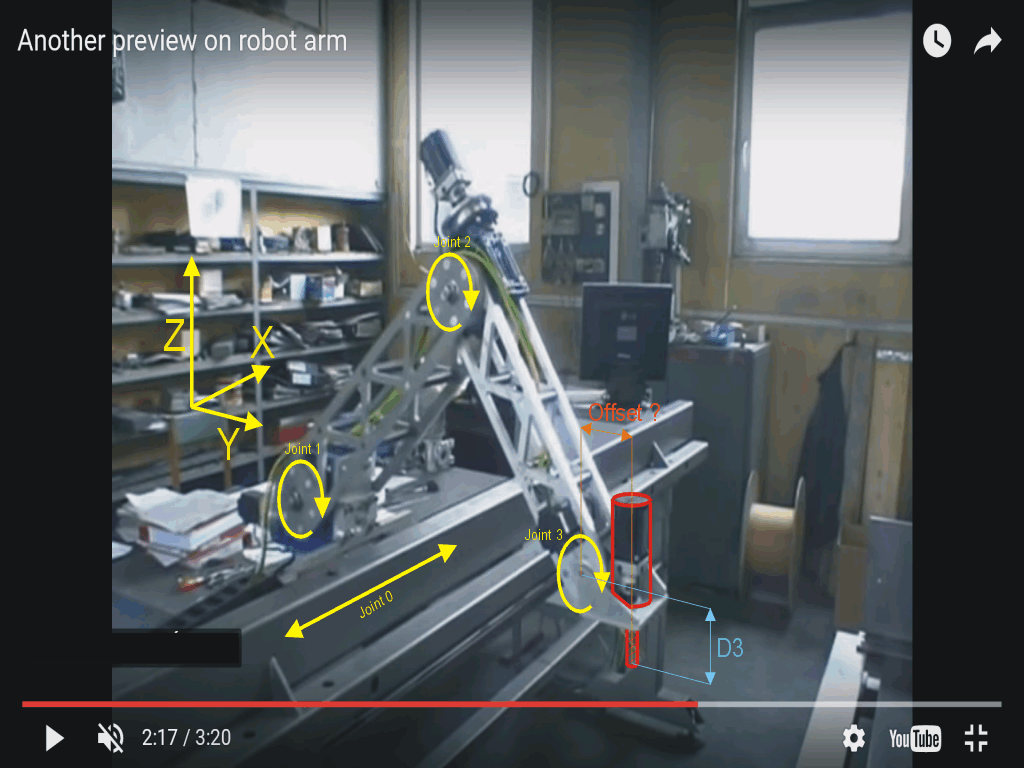
How about D3 vs ToolLenghtOffset and how about "Offset?"
Please Log in or Create an account to join the conversation.
LinuxCNC will automatically add the tool-Z to the Z-word in G-code. You probably don't want this. One way round this is to put the tool length in the tool table as a W-offset. Then feed the W-length into the kinematics from HAL to use in your calculations. This is _probably_ optional if you intend to keep the tool vertical, but if you intend to rotate about the A-axis then I think you need to do this.
Please Log in or Create an account to join the conversation.
regards
giorgio
Please Log in or Create an account to join the conversation.
joint[3] = End effector rotates around horizontal axis, that is
parallel to previous rotation axis and also X axis.
A value of zero means that the tooltip (if offset from the axis)
is pointing in the same direction as the centerline of the outer arm.
joint[4] = End effector rotates around horizontal axis, that is
perpendicular to previous rotation axis and is parallel to Y axis.
This module assumes there is no offset between joint[3] and joint[4] axes.
This model assumes THERE IS NO OFFSET between joint3 and joint4 - so this is the situation a drew here:
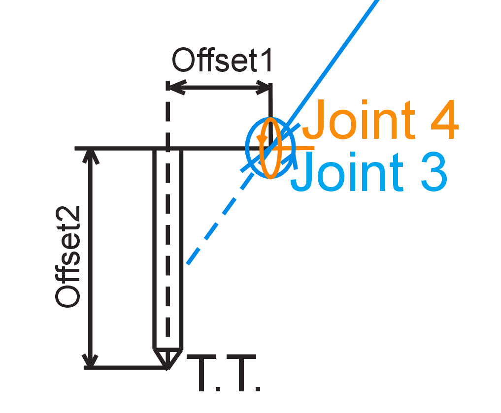
Joint3 rotation axis and joint4 rotation axis has common point and those axes are prependicular to each other and at the same time joint3 is parallel to Cartesian X and joint4 is parallel to Cartesian Y.
So if the assumption is there is no offset1, and that D3 is the distance from joint3&joint4rotational axes then it will look like this:

Guys am I reading robokins description in the right way?
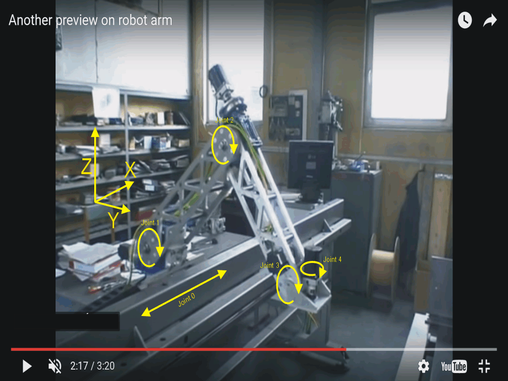
And this is not exactly what we see in the video, right? If I put spindle in place of that unused stepper motor (let's call it spindle platform) we can see in the video, Offset1 is not important AS LONG AS joints 1 thru 3 keep spindle platform PARALLEL to X-Y plane. In fact if i do not use A-axis (rotational around X-axis) that kinematics keeps spindle platform at constant angle in respect to X-Y plane. Am i clear?
Andy have you got INI and HAL files axamples for the kinematics you wrote for Viesturs? I can't contact him (no respond:()
Have a good day guys!
Please Log in or Create an account to join the conversation.
any how (using your label name on your post 17 May 2017 15:35 #9329) you have 2 offset ... the plane of joint3 is not the same of joint4 ... joint4 plane is 90° referred to joint3 plane + have 2 offset from centerline of each joint .... I'm quite sure that Andy make these calc on robokins (not remember now with precision, but i'm quite sure).
In your of "19 May 2017 10:22" your offset2 is only tool leght I think ..... or you install a some sort of tool after offset2 lenght?
After these .... you can able to work with joint0-1-2-3 only? these question for know if you have solve the configuration problem before furter exploring. For try you can eliminate every refer to join4 into robokins and try, or make joint4 equal to axis without cos calculation.... (for "cancel" you can use /* world...*/ way, so not delete it).
p.s. I'm reading better your mail .... if your plane where install the joint4 (is an axis or only a spindle?) why not use a parallelogram to keep the weight in place?
regards
giorgio
Please Log in or Create an account to join the conversation.
... if your plane where install the joint4 (is an axis or only a spindle?) why not use a parallelogram to keep the weight in place?
the answer is: parallelogram is mechanically complicated and more constrained in comparision with robokins mechatronics. And not suitable for future modifications if any needed.
Yes, you are right: in my case i don't want joint4. I want only a spindle in this place. And what i want from kinematics is to keep that spindle perpendicular to the X-Y plane.
Please Log in or Create an account to join the conversation.