SSI absolute encoders and analog servos

03 May 2016 09:44 #74167
by andypugh
The config string for hm2_pci is normally only needed if you want to turn off modules to make the pins usable as GPIO or to set the software data mode of some smart-serial devices.
I can't remember what the SSI driver does with no config string. You should probably try it with one to see if that makes the SSI pins show up.
The format of the config string is described here:
linuxcnc.org/docs/2.7/html/man/man9/hostmot2.9.html#Synchronous Serial Interface (SSI)
Replied by andypugh on topic SSI absolute encoders and analog servos
(4 SSI+4SSerial per 7I74 SSI channels first on 7I74 (0..3), SSerial last (4..7)) "
The config string for hm2_pci is normally only needed if you want to turn off modules to make the pins usable as GPIO or to set the software data mode of some smart-serial devices.
I can't remember what the SSI driver does with no config string. You should probably try it with one to see if that makes the SSI pins show up.
The format of the config string is described here:
linuxcnc.org/docs/2.7/html/man/man9/hostmot2.9.html#Synchronous Serial Interface (SSI)
Please Log in or Create an account to join the conversation.
03 May 2016 09:47 #74168
by andypugh
Replied by andypugh on topic SSI absolute encoders and analog servos
Can you paste the pin-description bit from dmesg too? That might be useful reference info.
[code]
sudo dmesg -c
halrun
loadrt hostmot2
loadrt hm2_pci
exit
dmesg[/quote]
Ignore the output of the first dmesg, and paste the output of the second one.
[code]
sudo dmesg -c
halrun
loadrt hostmot2
loadrt hm2_pci
exit
dmesg[/quote]
Ignore the output of the first dmesg, and paste the output of the second one.
Please Log in or Create an account to join the conversation.
10 Jun 2016 05:16 - 10 Jun 2016 05:17 #75746
by terkaa
Replied by terkaa on topic SSI absolute encoders and analog servos
Hi,
I have now made some progress and connected these card amongst many other things. I am now having following problem: It seems that Port 7 is only port working on 7i74. Any card I connect to this port starts blinking green after starting linuxcnc. Ports 4-6 remain red led on. Is it me or?
Tero
I have now made some progress and connected these card amongst many other things. I am now having following problem: It seems that Port 7 is only port working on 7i74. Any card I connect to this port starts blinking green after starting linuxcnc. Ports 4-6 remain red led on. Is it me or?


Tero
Last edit: 10 Jun 2016 05:17 by terkaa.
Please Log in or Create an account to join the conversation.
10 Jun 2016 08:02 #75748
by terkaa
Replied by terkaa on topic SSI absolute encoders and analog servos
Yes it was me. I had ssi_encoders statement on config line and that disabled all ports except no 7.
Tero
Tero
Please Log in or Create an account to join the conversation.
16 Aug 2016 14:54 - 16 Aug 2016 15:08 #78865
by terkaa
Replied by terkaa on topic SSI absolute encoders and analog servos
Hi,
Ok after 8 weeks of waiting I have now received Fagor G2 series absolute encoder with SSI output. I have flashed 5i25 with PCW's firmware. And now I have few questions:
1. How do I confirm that first 4 channels in 7i74 are now SSI inputs?
2. Actual hardware connection I have following pins out from encoder:
Gray = Data
Pink = /Data
Black = Clock
Purple = /Clock
Brown = +5V ( pin 7)
LT Green = + 5V Sensor ( Pin 8)
White = 0V (pin 4)
Orange = 0V Sensor ( pin 5)
What pins these connect on 7i74 RJ45 ?
3. And finally how to connect Y-position feedback pin to 7i74 channel 1 in config ?
Also here is pic of output specs:
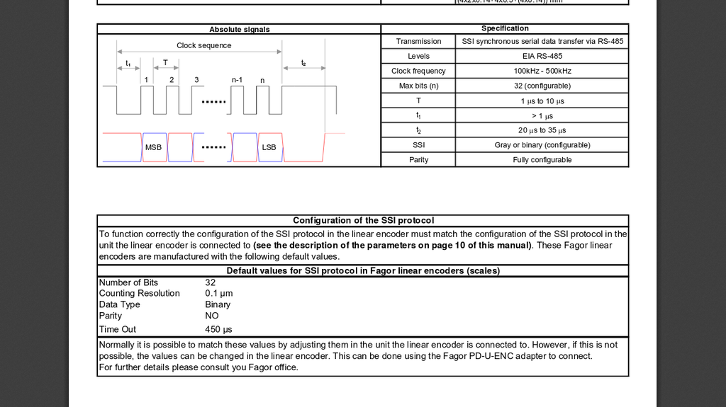
I requested 24 bit gray configuration.
Tero
Last edit: 16 Aug 2016 15:08 by terkaa.
Please Log in or Create an account to join the conversation.

16 Aug 2016 15:19 #78868
by PCW
Replied by PCW on topic SSI absolute encoders and analog servos
Let me check my Siemens SSI encoder, I have it wired to a RJ45
The first 4 RJ45s are SSI interfaces
(you can confirm this by running mesaflash with the --readhmid option in conjunction with the 7I74 manual))
The first 4 RJ45s are SSI interfaces
(you can confirm this by running mesaflash with the --readhmid option in conjunction with the 7I74 manual))
Please Log in or Create an account to join the conversation.
16 Aug 2016 23:35 #78915
by PCW
Replied by PCW on topic SSI absolute encoders and analog servos
TXA = 1 = Orange/White = SSI Clock
TXB = 2 = Orange = SSI /Clock
RXA = 3 = Green/White = SSI Data
RXB = 6 = Green = SSI /Data
5V and 5V sense to RJ45 7,8 (Brown,Brown/White)
0V and 0V sense to RJ45 4,5 (Blue,Blue/White)
( EIA/TIA 568B Colors )
TXB = 2 = Orange = SSI /Clock
RXA = 3 = Green/White = SSI Data
RXB = 6 = Green = SSI /Data
5V and 5V sense to RJ45 7,8 (Brown,Brown/White)
0V and 0V sense to RJ45 4,5 (Blue,Blue/White)
( EIA/TIA 568B Colors )
Please Log in or Create an account to join the conversation.
17 Aug 2016 05:35 #78916
by terkaa
Replied by terkaa on topic SSI absolute encoders and analog servos
Hi,
Ok thank. you. And configuration? I have now following lines in my HAL file:
loadrt hm2_pci config=" num_encoders=0 num_pwmgens=0 num_stepgens=0 sserial_port_1=00000000"
net Ypos axis.1.motor-pos-cmd => axis.1.motor-pos-fb ddt_y.in
How to change that to use channel 1 on sserial_port_1 for Y-pos feedback?
Also in INI:
# Second axis
[AXIS_1]
TYPE = LINEAR
HOME = 0.000
MAX_VELOCITY = 130
MAX_ACCELERATION = 508
BACKLASH = 0.000
INPUT_SCALE = 157.48
OUTPUT_SCALE = 1.000
MIN_LIMIT = -254
MAX_LIMIT = 254
FERROR = 1.27
MIN_FERROR = .254
HOME_OFFSET = 0.0
HOME_SEARCH_VEL = 0
HOME_LATCH_VEL = 0
HOME_USE_INDEX = NO
HOME_IGNORE_LIMITS = NO
HOME_SEQUENCE = 0
How to change that for Linear scale that has 0,1 um resolution?
Tero
Please Log in or Create an account to join the conversation.
17 Aug 2016 06:48 #78919
by terkaa
Replied by terkaa on topic SSI absolute encoders and analog servos
Also here is output of --readhmid
cinci@Cinci:~$ sudo mesaflash --device 5i25 --readhmid
Configuration Name: HOSTMOT2
General configuration information:
BoardName : MESA5I25
FPGA Size: 9 KGates
FPGA Pins: 144
Number of IO Ports: 2
Width of one I/O port: 17
Clock Low frequency: 33.3333 MHz
Clock High frequency: 200.0000 MHz
IDROM Type: 3
Instance Stride 0: 4
Instance Stride 1: 64
Register Stride 0: 256
Register Stride 1: 256
Modules in configuration:
Module: DPLL
There are 1 of DPLL in configuration
Version: 0
Registers: 7
BaseAddress: 7000
ClockFrequency: 33.333 MHz
Register Stride: 256 bytes
Instance Stride: 4 bytes
Module: WatchDog
There are 1 of WatchDog in configuration
Version: 0
Registers: 3
BaseAddress: 0C00
ClockFrequency: 33.333 MHz
Register Stride: 256 bytes
Instance Stride: 4 bytes
Module: IOPort
There are 2 of IOPort in configuration
Version: 0
Registers: 5
BaseAddress: 1000
ClockFrequency: 33.333 MHz
Register Stride: 256 bytes
Instance Stride: 4 bytes
Module: SSI
There are 8 of SSI in configuration
Version: 0
Registers: 4
BaseAddress: 6900
ClockFrequency: 33.333 MHz
Register Stride: 256 bytes
Instance Stride: 4 bytes
Module: SSerial
There are 2 of SSerial in configuration
Version: 0
Registers: 6
BaseAddress: 5B00
ClockFrequency: 33.333 MHz
Register Stride: 256 bytes
Instance Stride: 64 bytes
Module: LED
There are 1 of LED in configuration
Version: 0
Registers: 1
BaseAddress: 0200
ClockFrequency: 33.333 MHz
Register Stride: 256 bytes
Instance Stride: 4 bytes
Configuration pin-out:
IO Connections for P3
Pin# I/O Pri. func Sec. func Chan Pin func Pin Dir
1 0 IOPort SSI 0 Data (In)
14 1 IOPort SSI 1 Data (In)
2 2 IOPort SSI 2 Data (In)
15 3 IOPort SSI 3 Data (In)
3 4 IOPort SSI 0 SClk (Out)
16 5 IOPort SSI 1 SClk (Out)
4 6 IOPort SSI 2 SClk (Out)
17 7 IOPort SSI 3 SClk (Out)
5 8 IOPort SSerial 0 RXData2 (In)
6 9 IOPort SSerial 0 RXData3 (In)
7 10 IOPort SSerial 0 RXData4 (In)
8 11 IOPort SSerial 0 RXData5 (In)
9 12 IOPort SSerial 0 TXData2 (Out)
10 13 IOPort SSerial 0 TXData3 (Out)
11 14 IOPort SSerial 0 TXData4 (Out)
12 15 IOPort SSerial 0 TXData5 (Out)
13 16 IOPort SSerial 0 TXEn5 (Out)
IO Connections for P2
Pin# I/O Pri. func Sec. func Chan Pin func Pin Dir
1 17 IOPort SSI 4 Data (In)
14 18 IOPort SSI 5 Data (In)
2 19 IOPort SSI 6 Data (In)
15 20 IOPort SSI 7 Data (In)
3 21 IOPort SSI 4 SClk (Out)
16 22 IOPort SSI 5 SClk (Out)
4 23 IOPort SSI 6 SClk (Out)
17 24 IOPort SSI 7 SClk (Out)
5 25 IOPort SSerial 1 RXData2 (In)
6 26 IOPort SSerial 1 RXData3 (In)
7 27 IOPort SSerial 1 RXData4 (In)
8 28 IOPort SSerial 1 RXData5 (In)
9 29 IOPort SSerial 1 TXData2 (Out)
10 30 IOPort SSerial 1 TXData3 (Out)
11 31 IOPort SSerial 1 TXData4 (Out)
12 32 IOPort SSerial 1 TXData5 (Out)
13 33 IOPort SSerial 1 TXEn5 (Out)
Does this seem correct?
Tero
Please Log in or Create an account to join the conversation.
17 Aug 2016 15:54 #78950
by PCW
Replied by PCW on topic SSI absolute encoders and analog servos
That looks correct
You will probably need to start LinuxCNC and run a
halcmd show pin
to see whats working
Also the SSI encoders will need a setup string and clock speed setting
I think I have the example for my Siemens SSI encoder which is probably similar
You will probably need to start LinuxCNC and run a
halcmd show pin
to see whats working
Also the SSI encoders will need a setup string and clock speed setting
I think I have the example for my Siemens SSI encoder which is probably similar
Please Log in or Create an account to join the conversation.
Time to create page: 0.097 seconds