Spindle Control 6i25+7i76 and GS3-22P0 VFD RS-485 compatible?

04 Mar 2017 20:15 #89003
by Lcvette
Hello everyone,
I am finishing up my control cabinet build for my lathe and am using a Durapulse GS3-22P0 VFD and a vector duty 1.5hp marathon motor being controlled by LinuxCNC and Mesa 6i25+7i76 cards. I am pretty sure I can wire everything up using analog, but I have seen a few threads where RS-485 interface is better and more flexible. but I am not sure at this stage being very new to LinuxCNC if that is a smart direction for me to go if there isn't any support for that combination yet.
My complete setup will include the following to be considered in control and wiring.
the Motor has an encoder that is connected to a Feedback card installed in the VFD which will allow it to be full Vector control with feedback to the drive.
The spindle will have its own encoder, an Omron 3600ppr A,B,Z for spindle position and threading, this will be connected to the encoder input on the 7i76.
here is a link to the ModBus Manual for the GS3-22P0 VFD if anyone had questions about it:
GS3-22P0 ModBus Manual
So I guess what I am asking is if anyone has already connected this drive and had success and if so were there any hurdles or issues that made it more than a straight forward option? I ask because I am not experienced with ModBus or LinuxCNC so it is quite intimidating from looking through the manual.
Any input is very much appreciated!
Thanks,
Chris
Please Log in or Create an account to join the conversation.
04 Mar 2017 21:26 #89006
by Lcvette
Replied by Lcvette on topic Spindle Control 6i25+7i76 and GS3-22P0 VFD RS-485 compatible?
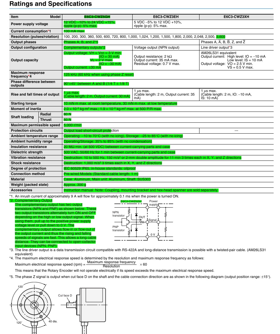
I goofed on the Encoder Purchase I think... it appears to be a Complementary type Encoder..is this typ encoder ok to use with the 7i76?
Link to Encoder Model Specifications: Omron E6C3-CWZ5GH
It has 5 wires:
Brown- Power Supply +Vcc 12vdc to 24vdc
Black- Output Phase A
White- Output Phase B
Orange- Output Phase Z
Blue- 0v Common
there are no wires for the A-, B-, Z-
Any thoughts?
Thanks in advance!
Chris
Link to Encoder Model Specifications: Omron E6C3-CWZ5GH
It has 5 wires:
Brown- Power Supply +Vcc 12vdc to 24vdc
Black- Output Phase A
White- Output Phase B
Orange- Output Phase Z
Blue- 0v Common
there are no wires for the A-, B-, Z-
Any thoughts?
Thanks in advance!
Chris
Please Log in or Create an account to join the conversation.
04 Mar 2017 21:34 #89007
by Lcvette
Replied by Lcvette on topic Spindle Control 6i25+7i76 and GS3-22P0 VFD RS-485 compatible?
now that i am looking at the 7i76 manual again, i see that the voltage for the encoder is 5v.. is that going to be an issue? I am getting flustered now.. not a cheap encoder to buy.... especially twice..grrr hopefully someone will chime in with some information and maybe a solution that doesn't require the purchase of another encoder..??? ")
Thanks,
Chris
Thanks,
Chris
Please Log in or Create an account to join the conversation.
- tommylight
-

- Offline
- Moderator
-

Less
More
- Posts: 17782
- Thank you received: 5909
04 Mar 2017 21:44 #89009
by tommylight
Replied by tommylight on topic Spindle Control 6i25+7i76 and GS3-22P0 VFD RS-485 compatible?
There is a solution, but at a risk of destroying the 7i76 encoder inputs, if you mess up somewhere.
You need 3 voltage dividers and a 12V power supply for the encoder or porer it from the same power supply as the VField to the 7i76.
Voltage dividers are simple resistors wired in series to the encoder outputs and to encoder inputs on the board, but not the same wires, newer the same wires for you case.
Just do a search for voltage divider using resistors, and you will also find how to calculate the values and how to wire it.
Regards,
Tom
Please Log in or Create an account to join the conversation.
05 Mar 2017 02:01 #89015
by Lcvette
Tom,
Thanks that is great news! any thoughts on the encoder being "Complementary" and only having outputs for the positive A,B,Z? wasn't sure if i could split the output to both the A+ and A- etc..?
I will be running the field voltage at 24v, I am guessing that doesn't matter when it comes to the encoder inputs on the 7i76 and they will need to be reduced via the voltage divider plan.. I am researching that now, but was hoping to verify the other aspect of the encoder.. picture of the information page on it below:


Thanks!
Chris
Replied by Lcvette on topic Spindle Control 6i25+7i76 and GS3-22P0 VFD RS-485 compatible?
There is a solution, but at a risk of destroying the 7i76 encoder inputs, if you mess up somewhere.
You need 3 voltage dividers and a 12V power supply for the encoder or porer it from the same power supply as the VField to the 7i76.
Voltage dividers are simple resistors wired in series to the encoder outputs and to encoder inputs on the board, but not the same wires, newer the same wires for you case.
Just do a search for voltage divider using resistors, and you will also find how to calculate the values and how to wire it.
Regards,
Tom
Tom,
Thanks that is great news! any thoughts on the encoder being "Complementary" and only having outputs for the positive A,B,Z? wasn't sure if i could split the output to both the A+ and A- etc..?
I will be running the field voltage at 24v, I am guessing that doesn't matter when it comes to the encoder inputs on the 7i76 and they will need to be reduced via the voltage divider plan.. I am researching that now, but was hoping to verify the other aspect of the encoder.. picture of the information page on it below:
Thanks!
Chris
Please Log in or Create an account to join the conversation.
05 Mar 2017 02:05 #89016
by Lcvette
Tom,
Thanks that is great news! although looking at the specifications page it appears that the encoder output is 3v? Am i reading this correctly? Also, any thoughts on the encoder being "Complementary" and only having outputs for the positive A,B,Z? wasn't sure if i could split the output to both the A+ and A- or if that would cause problems?
I will be running the field voltage at 24v, I am guessing that doesn't matter when it comes to the encoder inputs on the 7i76 and they will need to be reduced via the voltage divider plan.. I am researching that now, but was hoping to verify the other aspect of the encoder.. picture of the information page on it below:
Thanks!
Chris
Replied by Lcvette on topic Spindle Control 6i25+7i76 and GS3-22P0 VFD RS-485 compatible?
There is a solution, but at a risk of destroying the 7i76 encoder inputs, if you mess up somewhere.
You need 3 voltage dividers and a 12V power supply for the encoder or porer it from the same power supply as the VField to the 7i76.
Voltage dividers are simple resistors wired in series to the encoder outputs and to encoder inputs on the board, but not the same wires, newer the same wires for you case.
Just do a search for voltage divider using resistors, and you will also find how to calculate the values and how to wire it.
Regards,
Tom
Tom,
Thanks that is great news! although looking at the specifications page it appears that the encoder output is 3v? Am i reading this correctly? Also, any thoughts on the encoder being "Complementary" and only having outputs for the positive A,B,Z? wasn't sure if i could split the output to both the A+ and A- or if that would cause problems?
I will be running the field voltage at 24v, I am guessing that doesn't matter when it comes to the encoder inputs on the 7i76 and they will need to be reduced via the voltage divider plan.. I am researching that now, but was hoping to verify the other aspect of the encoder.. picture of the information page on it below:
Thanks!
Chris
Please Log in or Create an account to join the conversation.
- tommylight
-
- Offline
- Moderator
-
Less
More
- Posts: 17782
- Thank you received: 5909
05 Mar 2017 11:21 #89033
by tommylight
Replied by tommylight on topic Spindle Control 6i25+7i76 and GS3-22P0 VFD RS-485 compatible?
That is a single ended incremental encoder, and as far as i can recal all mesa boards have jumpers for using single ended encoders, so it should be ok, just check the 7i76 manualbto be sure.
On that diagram the Z output does not look like an index, in that case you can not use it for rigid taping, everything else should work.
On that diagram the Z output does not look like an index, in that case you can not use it for rigid taping, everything else should work.
Please Log in or Create an account to join the conversation.
06 Mar 2017 03:33 #89083
by Lcvette
OK it appears there are jumpers w4, w5, w6 to change to single ended encoders, I wasn't aware that's what this was.. so that's solved.. sweet!!
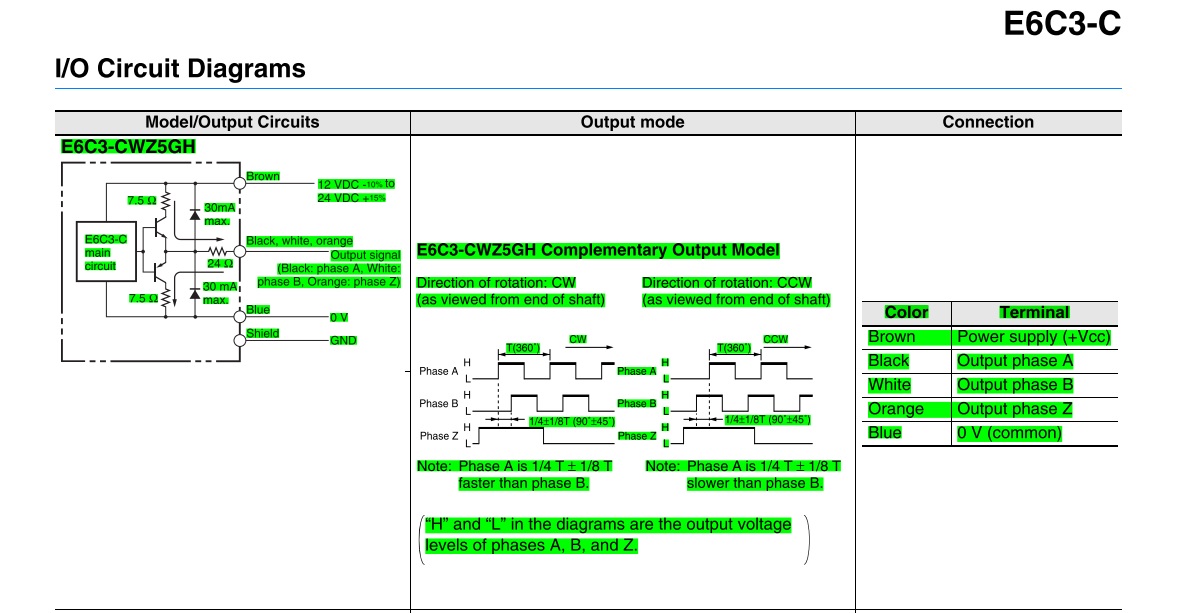
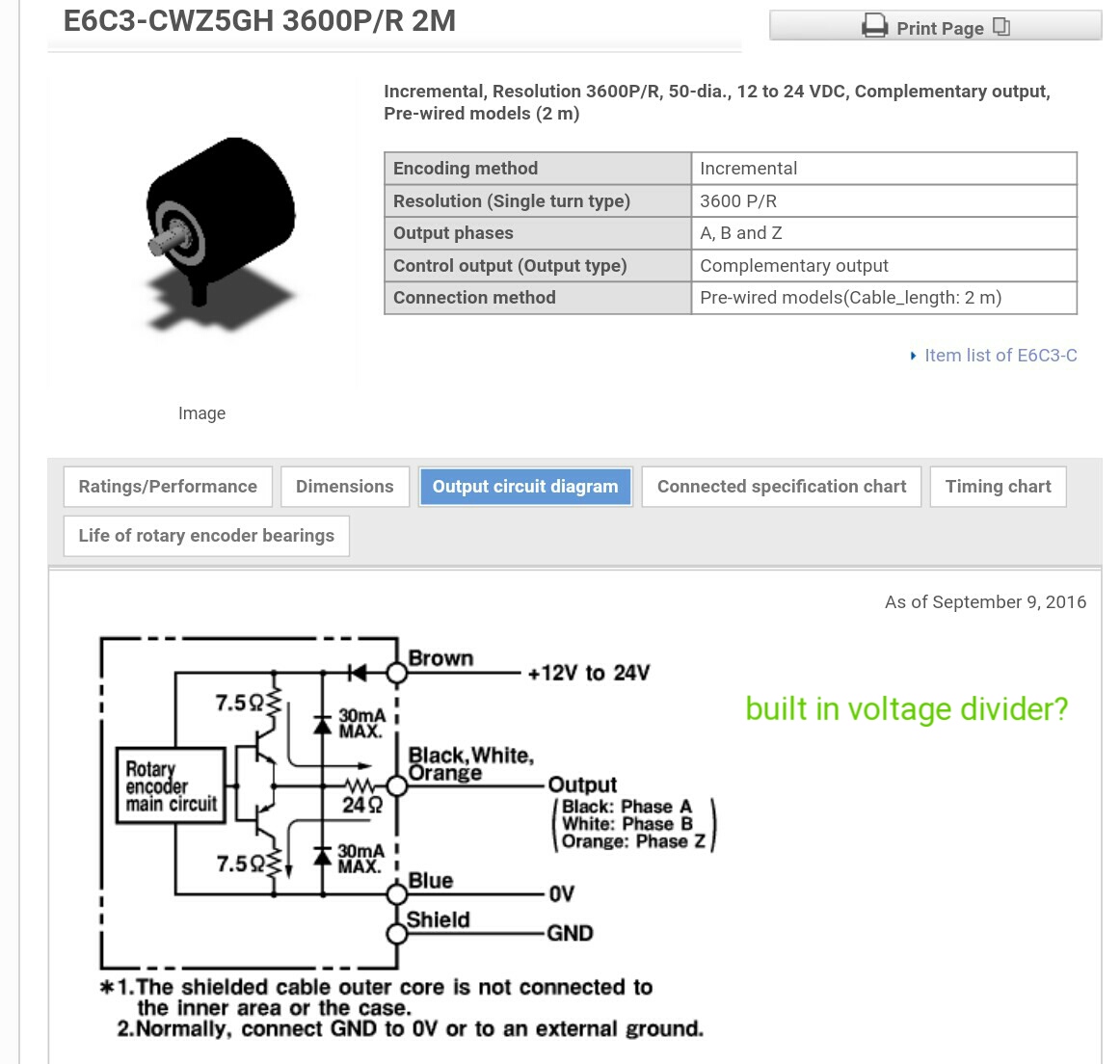
After combing through the specs again a few things jumped out at me. See the images below for reference, I marked them up with notes. I am not an electronics wiz, but from researching voltage dividers, it sort of appears that there are resistors being shown that are very close to achieving what a voltage divider would look like and the resistor sizes are very close to what the calculators are saying would be correct to do it to under 5v. Thoughts? I also saw where it shows the output as follows:
H- 3v min
L- 2v max
So I'm now wondering if the output is already the correct voltage, any thoughts here are great. I will contact omron tomorrow for verification as well.

Replied by Lcvette on topic Spindle Control 6i25+7i76 and GS3-22P0 VFD RS-485 compatible?
That is a single ended incremental encoder, and as far as i can recal all mesa boards have jumpers for using single ended encoders, so it should be ok, just check the 7i76 manualbto be sure.
On that diagram the Z output does not look like an index, in that case you can not use it for rigid taping, everything else should work.
OK it appears there are jumpers w4, w5, w6 to change to single ended encoders, I wasn't aware that's what this was.. so that's solved.. sweet!!
After combing through the specs again a few things jumped out at me. See the images below for reference, I marked them up with notes. I am not an electronics wiz, but from researching voltage dividers, it sort of appears that there are resistors being shown that are very close to achieving what a voltage divider would look like and the resistor sizes are very close to what the calculators are saying would be correct to do it to under 5v. Thoughts? I also saw where it shows the output as follows:
H- 3v min
L- 2v max
So I'm now wondering if the output is already the correct voltage, any thoughts here are great. I will contact omron tomorrow for verification as well.
Please Log in or Create an account to join the conversation.
- tommylight
-
- Offline
- Moderator
-
Less
More
- Posts: 17782
- Thank you received: 5909
06 Mar 2017 22:04 #89106
by tommylight
Replied by tommylight on topic Spindle Control 6i25+7i76 and GS3-22P0 VFD RS-485 compatible?
Here we go:
No changes to 7i76, no jumpers to move, just connect A, B, and Z, to the enc A+, enc B+, and Idx+. NOT directly !!!
Nothing in the outputs is 3V, IT IS 3V under the VCC ( in case of 12V it is 9V, in case of 24V it is 21V ) .
That is not a voltage divider, that is a "push-pull" output made of 2 transistors, so it can sink and source to the output.
Please read this before wiring the encoder,
learn.sparkfun.com/tutorials/voltage-dividers
make sure you understand how they should be wired and find some resistors that can be used as follows : You mentioned using 24V power, so to be sure that the current draw will not exceed 10mA and to easier calculate lets say a 2.4Kohm resistor (usual values 2.2 or 3.3 should do), now you need 3 to 5V at the encoder inputs on the 7i76 so that would imply 330 to 470 ohm . To recap, you need one 2.2KOhm and one 330 Ohm resistor for each channel, OR 3.3KOhm and 470Ohm.
On the pictures on that page you have Vin ( that is the output FROM the encoder ), Vout ( that is the input ON the 7i76 ) and the ground wire.
Please Log in or Create an account to join the conversation.
17 Mar 2017 13:28 #89821
by Lcvette
I wound up ordering a 5v encoder so I didn't make a mistake and wind up hiring something.
So going back to my original other question of VFD connection via the RS-485 connection. Is this something that is possible?
Replied by Lcvette on topic Spindle Control 6i25+7i76 and GS3-22P0 VFD RS-485 compatible?
Here we go:
No changes to 7i76, no jumpers to move, just connect A, B, and Z, to the enc A+, enc B+, and Idx+. NOT directly !!!
Nothing in the outputs is 3V, IT IS 3V under the VCC ( in case of 12V it is 9V, in case of 24V it is 21V ) .
That is not a voltage divider, that is a "push-pull" output made of 2 transistors, so it can sink and source to the output.
Please read this before wiring the encoder,
learn.sparkfun.com/tutorials/voltage-dividers
make sure you understand how they should be wired and find some resistors that can be used as follows : You mentioned using 24V power, so to be sure that the current draw will not exceed 10mA and to easier calculate lets say a 2.4Kohm resistor (usual values 2.2 or 3.3 should do), now you need 3 to 5V at the encoder inputs on the 7i76 so that would imply 330 to 470 ohm . To recap, you need one 2.2KOhm and one 330 Ohm resistor for each channel, OR 3.3KOhm and 470Ohm.
On the pictures on that page you have Vin ( that is the output FROM the encoder ), Vout ( that is the input ON the 7i76 ) and the ground wire.
I wound up ordering a 5v encoder so I didn't make a mistake and wind up hiring something.
So going back to my original other question of VFD connection via the RS-485 connection. Is this something that is possible?
Please Log in or Create an account to join the conversation.
Time to create page: 0.256 seconds