DMM DYN 4 servos + Mesa 5i25 & 7i77 XYZ+A Cnc 5x10
23 May 2015 10:21 - 17 Mar 2016 18:17 #58947
by ROB-CNC
Replied by ROB-CNC on topic DMM DYN 4 servos + Mesa 5i25 & 7i77 XYZ+A Cnc 5x10
So I changed the wiring and tested...
Now I believe the drive is constantly disabled. I can freely spin the motor shaft by hand while servo is powered which would normally suggest that the drive is disabled. Before that the shaft was locked.
Also, even though the servo is disabled (shaft moves freely) I can still get LinuxCNC to give it signal and make it spin. Weird. I'm quite confused now and not sure what is going on with the enable/disable in the drive.
Last edit: 17 Mar 2016 18:17 by ROB-CNC.
Please Log in or Create an account to join the conversation.
23 May 2015 20:15 #58953
by alan_3301
Replied by alan_3301 on topic DMM DYN 4 servos + Mesa 5i25 & 7i77 XYZ+A Cnc 5x10
ok it looks like it is actually a disable input.
I don't know why they say active high, but the sample diagram shows sinking input.
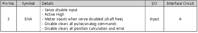
maybe a way to invert the enable on the 7i77?
I don't know why they say active high, but the sample diagram shows sinking input.
maybe a way to invert the enable on the 7i77?
The following user(s) said Thank You: ROB-CNC
Please Log in or Create an account to join the conversation.

23 May 2015 22:53 - 23 May 2015 23:02 #58956
by PCW
Replied by PCW on topic DMM DYN 4 servos + Mesa 5i25 & 7i77 XYZ+A Cnc 5x10
For a disable input you need an external inverter like a normally closed relay:
+24V --> Relay-COM --> Relay-NC --> Disable-Input
and perhaps drive the relay coil from one of the field I/O outputs
Another possibility is wiring the disable input with a say 1K 2W
pull-up resistor to +24V and then grounding it with the 7I77s ENA pins:
+24V --> 1K Resistor.1 --> 1K Resistor.2 --> Disable-Input & 7I77ENA+
7I77ENA- --> GND
Edit:
The reason you can't simply invert the enables is that the 7I77s non-powered
and startup state should disable the drives and this is not easy to do with OPTOs
which are 'OFF' when not powered
Form B OPTOs = normally closed are available but rather exotic and
this would require a special 7I77 version.
Last edit: 23 May 2015 23:02 by PCW.
The following user(s) said Thank You: ROB-CNC
Please Log in or Create an account to join the conversation.
24 May 2015 00:03 - 17 Mar 2016 18:13 #58957
by ROB-CNC
Replied by ROB-CNC on topic DMM DYN 4 servos + Mesa 5i25 & 7i77 XYZ+A Cnc 5x10
Thanks for the replies guys.
I will work on the machine today as I have some free time... I am going to search the parts bin for a good relay to try and invert the ENA signal.
I will work on the machine today as I have some free time... I am going to search the parts bin for a good relay to try and invert the ENA signal.
Last edit: 17 Mar 2016 18:13 by ROB-CNC.
Please Log in or Create an account to join the conversation.
28 May 2015 02:21 #59121
by ROB-CNC
Replied by ROB-CNC on topic DMM DYN 4 servos + Mesa 5i25 & 7i77 XYZ+A Cnc 5x10
I spent the weekend working on the mechanical side, mainly on the Z-axis... I configured the servos and will need to tune them soon.
Anyways, I have not worked on getting the enable signal to work correctly as I got side tracked working on other parts of the machine.
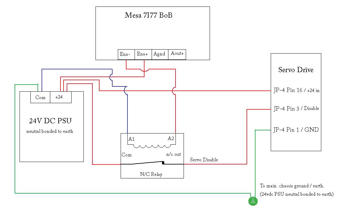
I have attached a wiring diagram of how I think I could get the enabled reversed for disable. I would like to see if the way I have it wired in the diagram would work correctly... I thought it would be best to ask you guys before I do it so that I do not damage the 7I77 board or drive by doing something wrong.
@PCW I understand the way you suggested to wire up the relay but would I not need to wire the coil to the ENA- so that the drive will enable when Linuxcnc sends out a enable command? I might not be understanding something correctly.
Thanks!
Anyways, I have not worked on getting the enable signal to work correctly as I got side tracked working on other parts of the machine.
I have attached a wiring diagram of how I think I could get the enabled reversed for disable. I would like to see if the way I have it wired in the diagram would work correctly... I thought it would be best to ask you guys before I do it so that I do not damage the 7I77 board or drive by doing something wrong.
@PCW I understand the way you suggested to wire up the relay but would I not need to wire the coil to the ENA- so that the drive will enable when Linuxcnc sends out a enable command? I might not be understanding something correctly.
Thanks!
Please Log in or Create an account to join the conversation.
28 May 2015 02:53 #59125
by alan_3301
Replied by alan_3301 on topic DMM DYN 4 servos + Mesa 5i25 & 7i77 XYZ+A Cnc 5x10
That looks good to me, but I would wait for a more confident answer.
What do you mean when you say the neutral is bonded to earth.
If it's a 120V input power supply, it should have L1 and L2 inputs connected to 120V and Neutral. The case should be connected to ground.
You aren't supposed to have neutral and ground connected together anywhere but at the main service entrance.
Please Log in or Create an account to join the conversation.
28 May 2015 02:59 #59126
by alan_3301
Replied by alan_3301 on topic DMM DYN 4 servos + Mesa 5i25 & 7i77 XYZ+A Cnc 5x10
Also, I wouldn't think jp4 pin 1 should be connected to earth ground.
It is used as a reference for the monitors on pins 8, 20, and 21.
you may want to ask dmm about that.
I would leave disconnected unless you are going to wire the monitors up, in that case I would connect it directly to the field power supply negative terminal.
It is used as a reference for the monitors on pins 8, 20, and 21.
you may want to ask dmm about that.
I would leave disconnected unless you are going to wire the monitors up, in that case I would connect it directly to the field power supply negative terminal.
The following user(s) said Thank You: ROB-CNC
Please Log in or Create an account to join the conversation.
28 May 2015 03:17 - 17 Mar 2016 18:07 #59127
by ROB-CNC
Replied by ROB-CNC on topic DMM DYN 4 servos + Mesa 5i25 & 7i77 XYZ+A Cnc 5x10
Hi Alan,
What I meant is that the 24v dc common is bonded to ground, this is to help reduce noise in the system. I've been told it is good practice to bond all low voltage dc psu commons to earth ground. There are no high voltage lines tied to the machine ground as that is not a good idea.
Thanks.
What I meant is that the 24v dc common is bonded to ground, this is to help reduce noise in the system. I've been told it is good practice to bond all low voltage dc psu commons to earth ground. There are no high voltage lines tied to the machine ground as that is not a good idea.
Thanks.
Last edit: 17 Mar 2016 18:07 by ROB-CNC.
Please Log in or Create an account to join the conversation.
28 May 2015 03:32 - 17 Mar 2016 18:05 #59128
by ROB-CNC
Replied by ROB-CNC on topic DMM DYN 4 servos + Mesa 5i25 & 7i77 XYZ+A Cnc 5x10
In regards to pin 1 ground, I had the same assumption. Pins 1,9,12 are all tied to the JP4 connector shell internally in the drive so I assumed It would be fine to use pin 1 to connect the cable shield since they have it tied to the connector shell anyways.
Last edit: 17 Mar 2016 18:05 by ROB-CNC.
Please Log in or Create an account to join the conversation.
28 May 2015 23:03 #59157
by alan_3301
Replied by alan_3301 on topic DMM DYN 4 servos + Mesa 5i25 & 7i77 XYZ+A Cnc 5x10
I saw your post on cnczone, made me think about it more
Dmm calls the enable input active high. When described as disable input on the other diagram, it shows ground to activate.
So.. instead of 24v being switched by the relay to jp4 pin3, It makes sense to me to send ground down that wire to the relay contacts.
Normally closed relay, ground passing through - Disabled.
relay active, open circuit, drive pulls the line high - Enabled.
maybe try that?
The following user(s) said Thank You: ROB-CNC
Please Log in or Create an account to join the conversation.
Moderators: cncbasher
Time to create page: 0.101 seconds