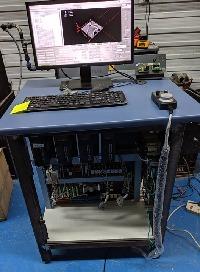
Biesse Rover 346 Retrofit
08 Feb 2017 15:49 - 08 Feb 2017 15:55 #87573
by bevins
Replied by bevins on topic Biesse Rover 346 Retrofit
OK, I am pulling my hair out now....... and I have none....
I cant get it to home properly. Can you check my ini? I tried all the possibilities. I have the UCS ok now, X,Y 0,0 top left.
I am getting these errors. I attached my ini file.
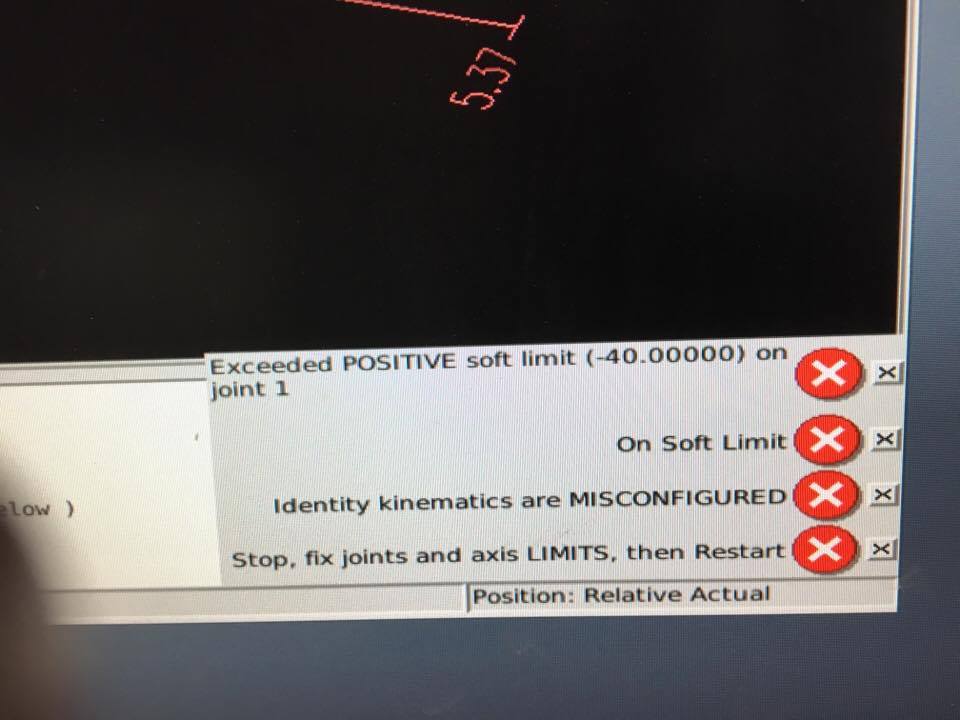
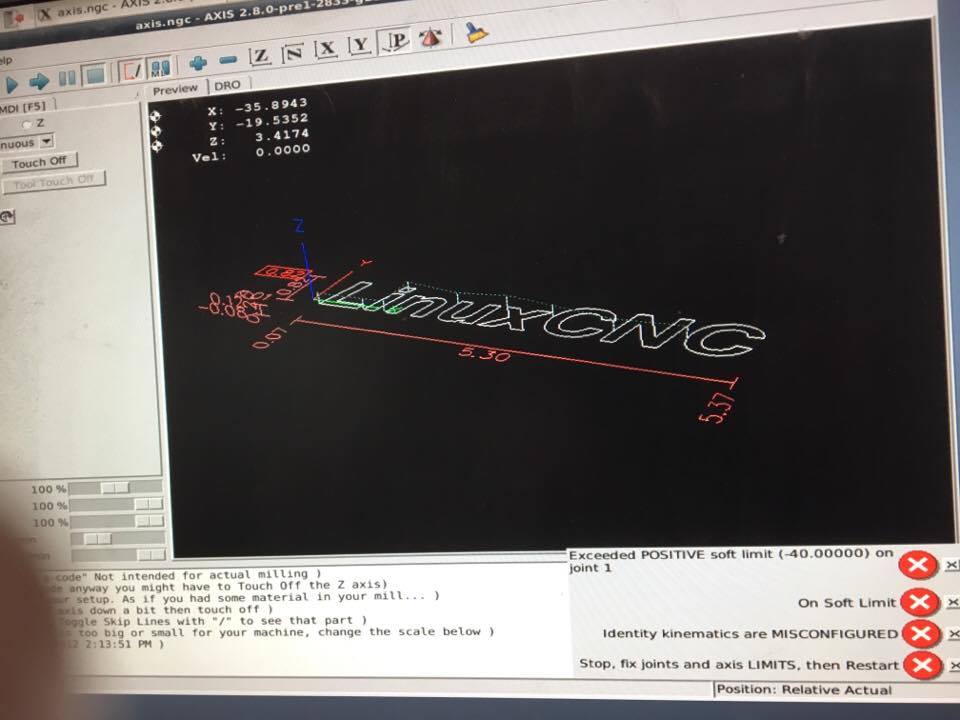
Looking at it again, it thinks it is at the other end of the Y. -40 is soft limit away from the home, but it LinuxCNC is thinking opposite.
What have I got backwards?
I cant get it to home properly. Can you check my ini? I tried all the possibilities. I have the UCS ok now, X,Y 0,0 top left.
I am getting these errors. I attached my ini file.
Looking at it again, it thinks it is at the other end of the Y. -40 is soft limit away from the home, but it LinuxCNC is thinking opposite.
What have I got backwards?
Last edit: 08 Feb 2017 15:55 by bevins.
Please Log in or Create an account to join the conversation.
- Todd Zuercher
-

- Away
- Platinum Member
-

Less
More
- Posts: 4963
- Thank you received: 1369
08 Feb 2017 16:11 - 08 Feb 2017 16:14 #87577
by Todd Zuercher
Replied by Todd Zuercher on topic Biesse Rover 346 Retrofit
Just change this for your Y and joint1
MIN_LIMIT =-40.0 (was 0.01)
MAX_LIMIT = 0.01 (was -40.0)
MIN_LIMIT =-40.0 (was 0.01)
MAX_LIMIT = 0.01 (was -40.0)
Last edit: 08 Feb 2017 16:14 by Todd Zuercher.
Please Log in or Create an account to join the conversation.
08 Feb 2017 16:59 #87587
by bevins
I did that and swapped the sign for searching and all is well. I dont understand what happened but it is all fixed. I think I was changing things and changing the required mating pair that needed it. Anyway all is good.
Ran some Gcode and it is working.
On to the spindle/inverter and switching spindles.....ARRKKK...... It doesnt get any easier from here....lol
Replied by bevins on topic Biesse Rover 346 Retrofit
Just change this for your Y and joint1
MIN_LIMIT =-40.0 (was 0.01)
MAX_LIMIT = 0.01 (was -40.0)
I did that and swapped the sign for searching and all is well. I dont understand what happened but it is all fixed. I think I was changing things and changing the required mating pair that needed it. Anyway all is good.
Ran some Gcode and it is working.
On to the spindle/inverter and switching spindles.....ARRKKK...... It doesnt get any easier from here....lol
Please Log in or Create an account to join the conversation.
08 Feb 2017 17:09 #87588
by bevins
Replied by bevins on topic Biesse Rover 346 Retrofit
Whats left to do is the following:
1. Spindle / inverter and switching (3 spindles on this head)
2. Tool Changer
3. Aggregate and horizontal and boring motors
4. Logic for the pods and accessories.
Three Spindles
Horizontal and Vertical Boring heads. 32 heads with capability to drop each individually.
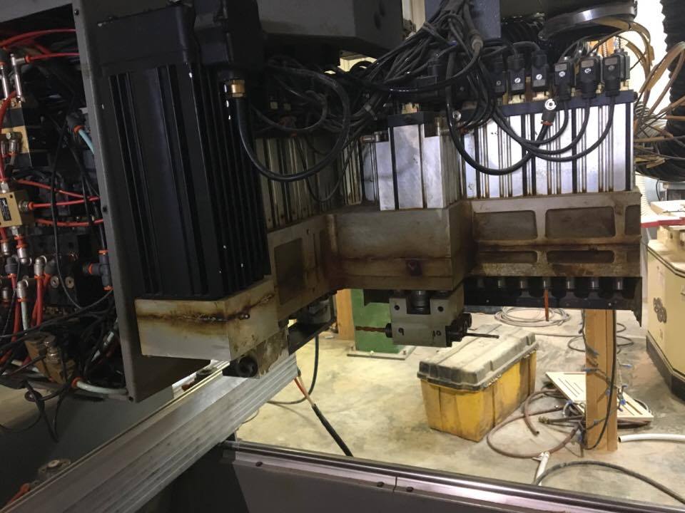
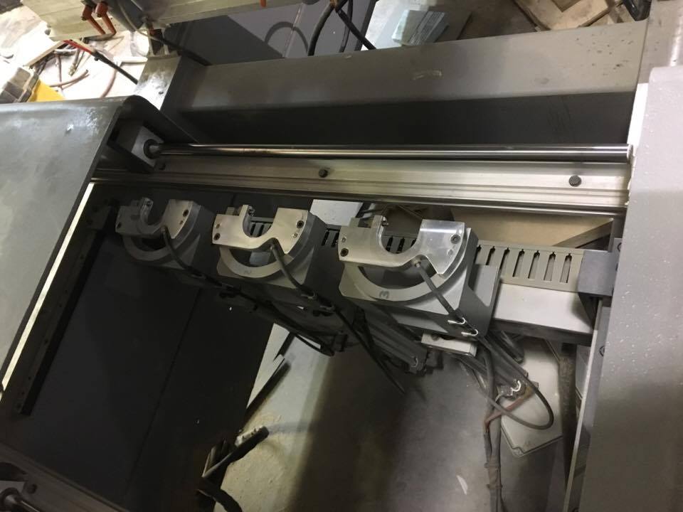
3 position tool changer. Three spindles so need to keep one open at all times so it has the capability of 5 tools.
It also has the provision to add more if required.
1. Spindle / inverter and switching (3 spindles on this head)
2. Tool Changer
3. Aggregate and horizontal and boring motors
4. Logic for the pods and accessories.
Three Spindles
Horizontal and Vertical Boring heads. 32 heads with capability to drop each individually.
3 position tool changer. Three spindles so need to keep one open at all times so it has the capability of 5 tools.
It also has the provision to add more if required.
Please Log in or Create an account to join the conversation.
- Todd Zuercher
-
- Away
- Platinum Member
-
Less
More
- Posts: 4963
- Thank you received: 1369
08 Feb 2017 18:44 #87590
by Todd Zuercher
Replied by Todd Zuercher on topic Biesse Rover 346 Retrofit
3 spindles and 3 tool positions. Do all three spindles need to be able to access the tool change rack, or only one of the spindles?
If all three, that sounds complicated, kind of like a random tool changer with a twist.
I think I'd just set up the drill bank to use a custom M-code (M1xxPxx)to select and lower the tool) and a T code (to set the offsets). (not sure how it would exactly all shake out.)
If all three, that sounds complicated, kind of like a random tool changer with a twist.
I think I'd just set up the drill bank to use a custom M-code (M1xxPxx)to select and lower the tool) and a T code (to set the offsets). (not sure how it would exactly all shake out.)
Please Log in or Create an account to join the conversation.
08 Feb 2017 20:10 #87596
by bevins
I would be ok just changing the bit in spindle one, and keep same bit in spindle 2 and 3.
Replied by bevins on topic Biesse Rover 346 Retrofit
3 spindles and 3 tool positions. Do all three spindles need to be able to access the tool change rack, or only one of the spindles?
If all three, that sounds complicated, kind of like a random tool changer with a twist.
I think I'd just set up the drill bank to use a custom M-code (M1xxPxx)to select and lower the tool) and a T code (to set the offsets). (not sure how it would exactly all shake out.)
I would be ok just changing the bit in spindle one, and keep same bit in spindle 2 and 3.
Please Log in or Create an account to join the conversation.
- Todd Zuercher
-
- Away
- Platinum Member
-
Less
More
- Posts: 4963
- Thank you received: 1369
08 Feb 2017 20:54 #87598
by Todd Zuercher
Replied by Todd Zuercher on topic Biesse Rover 346 Retrofit
That would be the easy way, but I think it could still be done thinking of it similarly to a random tool changer model.
You would have 6 possible tool positions that would be analogous to a random tool changer's pockets. The first 3 positions would be spindle#1, #2 and #3, then the 3 rack positions. Then you would have your tool numbers 0-5, with 0 being the empty space holder. Tools are changed by exchanging T0 with the other tools and the tool table automagicly keeps track of where every thing is. I don't know if you would need to do a remap of M6 to make this work or not.
Andy was working on some stuff pertaining to multiple spindle arrangements recently for addition to Master. Perhaps he will chime in with advice and whether or not what he was working on would be applicable to your system.
Please Log in or Create an account to join the conversation.
- Todd Zuercher
-
- Away
- Platinum Member
-
Less
More
- Posts: 4963
- Thank you received: 1369
08 Feb 2017 21:02 #87600
by Todd Zuercher
Replied by Todd Zuercher on topic Biesse Rover 346 Retrofit
The more I think about it, it probably isn't worth the effort. Whether or not you can auto tool change each spindle makes no difference in the number of tools you can run, it is still only a max of 5 tools if you can only change spindle #1 or all 3. Maybe if you had a lot more tool positions available, it might be worth the effort for parallel milling, but as it is you can't even do one tool change to each spindle.
Please Log in or Create an account to join the conversation.
09 Feb 2017 00:30 #87625
by bevins
I have provisions for adding more. The tool changer has the capability of 15 tools. I am going to add some, dont know how many but...
Your thoughts have some legitity. The only thing it saves is having to travel from one side of the machine to the other. Time savings.
If you have a program that needs 4 tools, one in each spindle plus another one. If you are on the other side of the machine cutting, and a tool change comes up you would have to go back anyway and change out the tool that is not in one of the spindles.
I dont have a problem leaving the most used bits in spindle 2 and 3 and using spindle 1 to change tools when needed.
Replied by bevins on topic Biesse Rover 346 Retrofit
The more I think about it, it probably isn't worth the effort. Whether or not you can auto tool change each spindle makes no difference in the number of tools you can run, it is still only a max of 5 tools if you can only change spindle #1 or all 3. Maybe if you had a lot more tool positions available, it might be worth the effort for parallel milling, but as it is you can't even do one tool change to each spindle.
I have provisions for adding more. The tool changer has the capability of 15 tools. I am going to add some, dont know how many but...
Your thoughts have some legitity. The only thing it saves is having to travel from one side of the machine to the other. Time savings.
If you have a program that needs 4 tools, one in each spindle plus another one. If you are on the other side of the machine cutting, and a tool change comes up you would have to go back anyway and change out the tool that is not in one of the spindles.
I dont have a problem leaving the most used bits in spindle 2 and 3 and using spindle 1 to change tools when needed.
Please Log in or Create an account to join the conversation.
09 Feb 2017 15:01 - 09 Feb 2017 15:34 #87662
by bevins
Replied by bevins on topic Biesse Rover 346 Retrofit
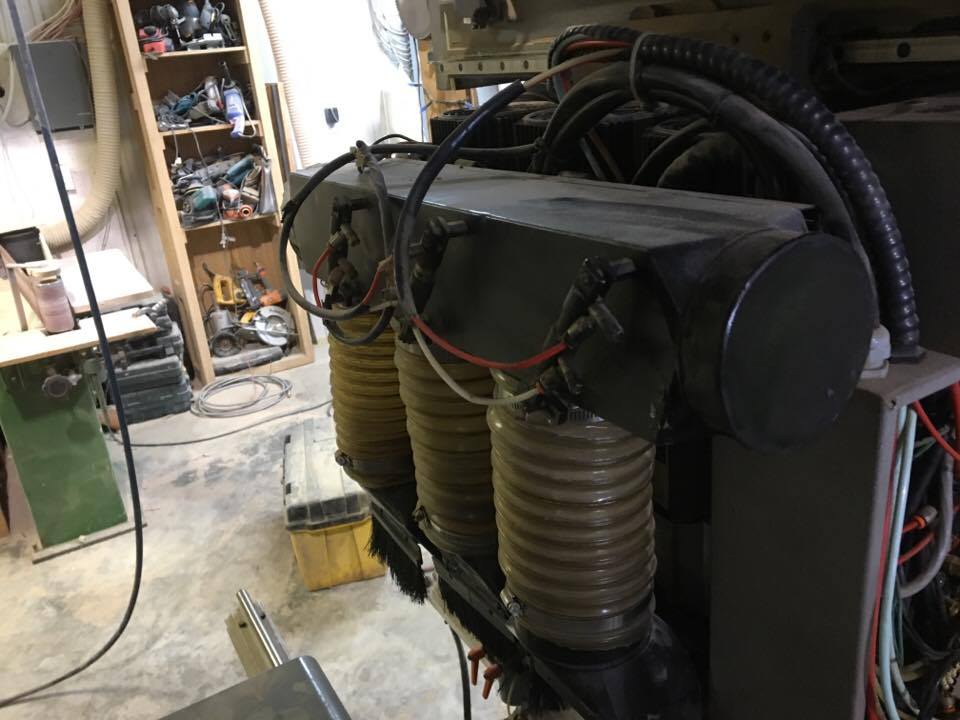
Today is spindle day.......
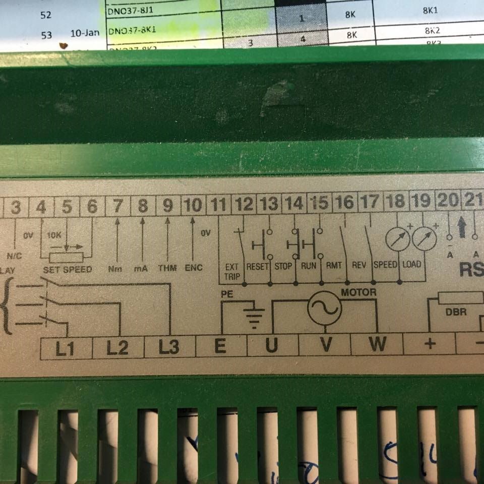
I have a cControl Techniques inverter Commander-CD-750.
It has a POT option. It was running with RS485 from the old control. I am going to attempt to use the pot interface and control it via 7i77 spindle with 0-10v.
My plan is to connect 0-10v from 7i77 to pins 4 and 5.
Then run pins 11 and 18 into analog input on 7i77 to get spindle at speed so the program can continue.
Then somehow when the spindle out is set in Gcode fire a oneshot relay on pins 11 and 15.
then when spindle is shutdown, fire a relay oneshot and open pin 14 and 11.
Does this sound correct?
Questions:
1. With regards to a 7i77, which bit on sserial_port_0 do I need to get the analog inputs? 0=200xxx ?
loadrt hm2_pci config=" num_encoders=6 num_pwmgens=0 num_stepgens=0 sserial_port_0=000xxx sserial_port_1=00000000"
EDIT
Found it.
loadrt hm2_pci config=" num_encoders=6 num_pwmgens=0 num_stepgens=0 sserial_port_0=200xxx sserial_port_1=00000000"
That should make inputs 0-3 on 7i77 as analog.
/EDIT
Last edit: 09 Feb 2017 15:34 by bevins.
Please Log in or Create an account to join the conversation.
Time to create page: 0.191 seconds