HELP WITH BOSCH ANALOG DC SERVOS
02 Mar 2017 10:07 #88864
by Yannis
HELP WITH BOSCH ANALOG DC SERVOS was created by Yannis
the reason to try to learn linux cnc is that i have 2 sets of analog dc and ac servomotors
(3 pcs dc of bosch and 3 pcs ac from drive system) and i woold like to use them
for converting a marble bridge saw to 4 or 5 axis bridge saw cnc
after little search in the forum ithink that a 5i25+7i77 is a good choise
I ALLREADY ORDER THE 5i25+7i77
HERE SOME PHOTOS OF THE MOTOR AND THE DRIVERS
THE SET IS FROM A WOOD ROUTER

THE ONLY USER MANUAL IN THE WEB IS IN GERMAN AND IS NOT HELPING
ANY SUGESTION ?
THANKS
(3 pcs dc of bosch and 3 pcs ac from drive system) and i woold like to use them
for converting a marble bridge saw to 4 or 5 axis bridge saw cnc
after little search in the forum ithink that a 5i25+7i77 is a good choise
I ALLREADY ORDER THE 5i25+7i77
HERE SOME PHOTOS OF THE MOTOR AND THE DRIVERS
THE SET IS FROM A WOOD ROUTER
THE ONLY USER MANUAL IN THE WEB IS IN GERMAN AND IS NOT HELPING
ANY SUGESTION ?
THANKS
Please Log in or Create an account to join the conversation.

06 Mar 2017 23:23 - 06 Mar 2017 23:25 #89114
by andypugh
Replied by andypugh on topic HELP WITH BOSCH ANALOG DC SERVOS
This seems to be in English.
You don't say what language you would prefer?
www.rgbautomatyka.pl/de/p/file/a8aa949cc...RVO-MOTOR-manual.pdf
You don't say what language you would prefer?
www.rgbautomatyka.pl/de/p/file/a8aa949cc...RVO-MOTOR-manual.pdf
Last edit: 06 Mar 2017 23:25 by andypugh.
The following user(s) said Thank You: Yannis
Please Log in or Create an account to join the conversation.
07 Mar 2017 20:22 #89161
by Yannis
Replied by Yannis on topic HELP WITH BOSCH ANALOG DC SERVOS
thanks
i m waiting for the MESA5I25 7I77 this week
do you now the right connection for this servos?
Yannis
i m waiting for the MESA5I25 7I77 this week
do you now the right connection for this servos?
Yannis
Please Log in or Create an account to join the conversation.
08 Mar 2017 19:32 #89215
by Henk
Replied by Henk on topic HELP WITH BOSCH ANALOG DC SERVOS
Hi. I used similar drives in my Deckel. Im also using a 7i77. The manual in the link explains the connections and from what i see in the photos above the connections to your drives will be the same as in the manual.
The following user(s) said Thank You: Yannis
Please Log in or Create an account to join the conversation.
19 Apr 2017 19:39 #91669
by Yannis
Replied by Yannis on topic HELP WITH BOSCH ANALOG DC SERVOS
hi Henk
i make my first attempt to connect the driver and the motors with no success
do you have also the same motors??
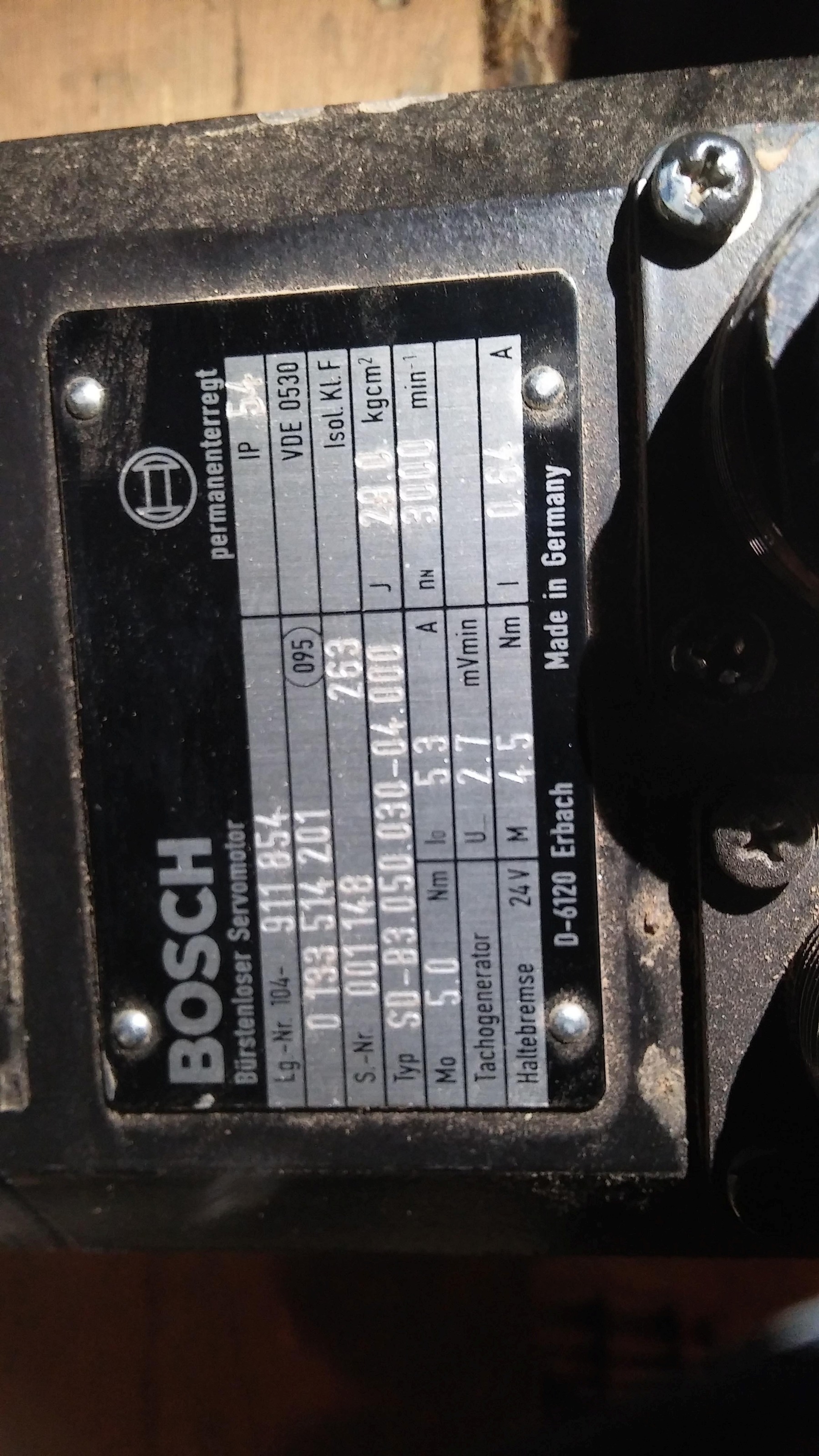
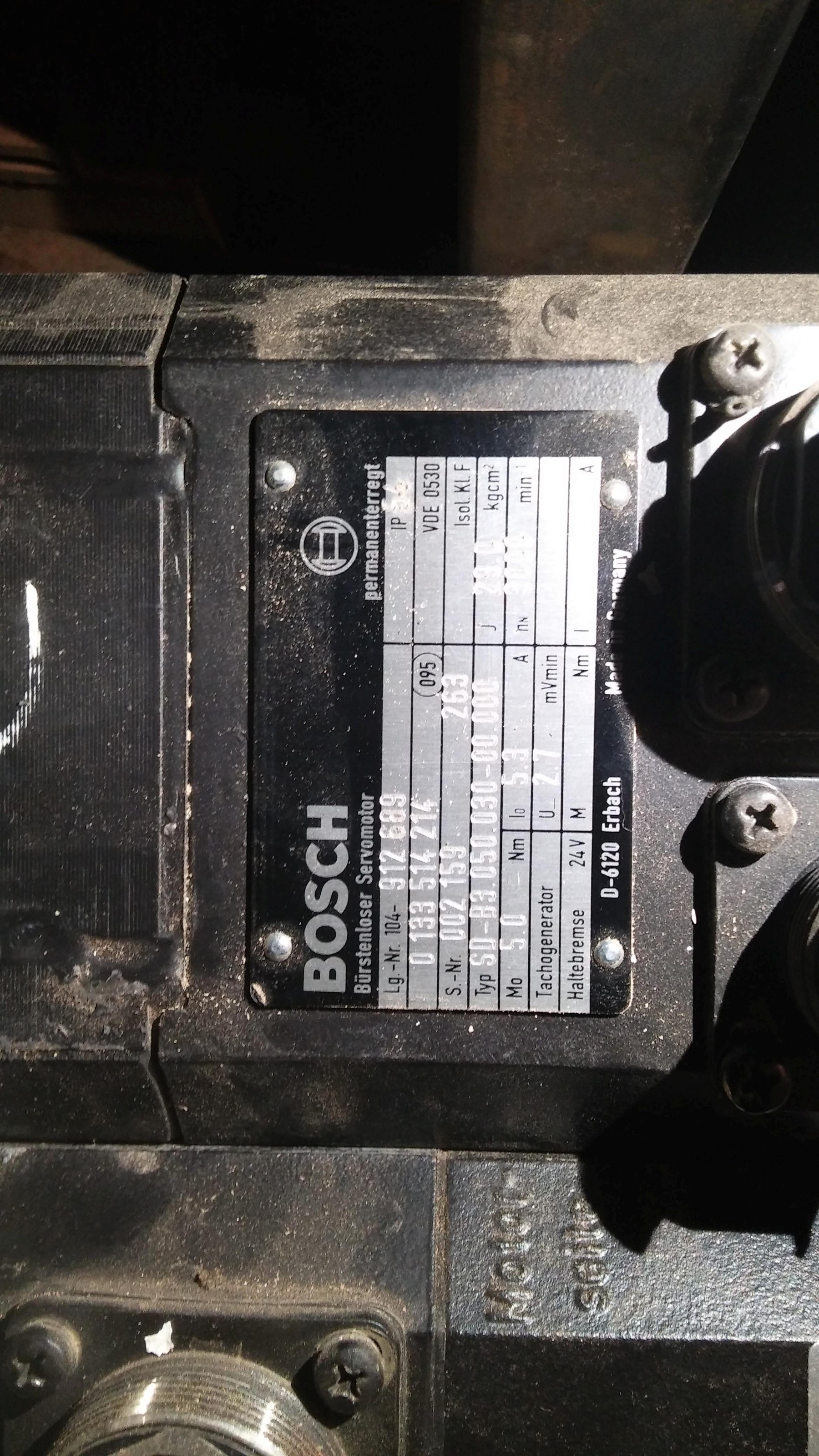
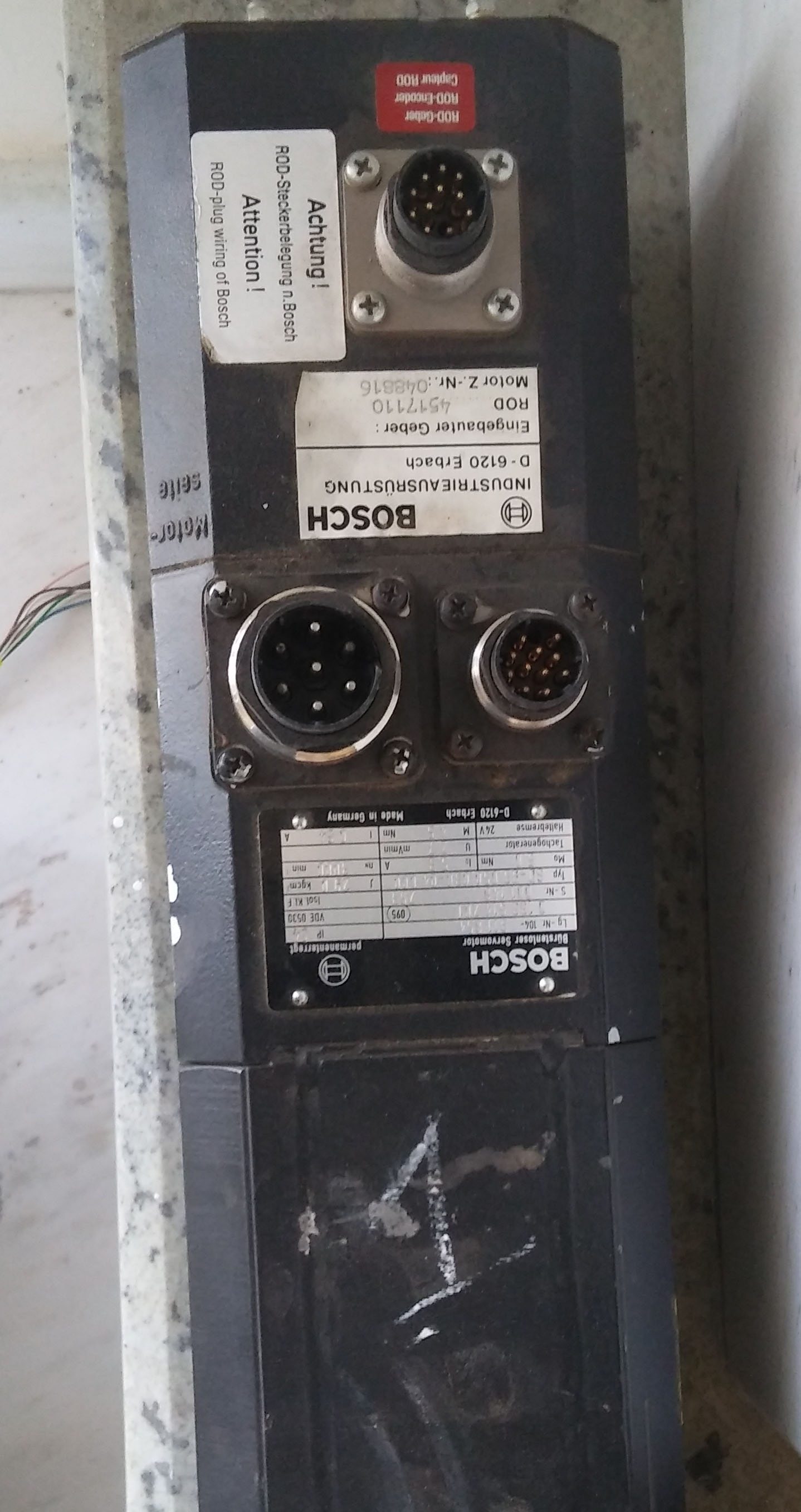
as you can see in the motor there is 3 connections and i don't have a user manual for the motors
because i don't now what to expect
i don't now how to start
what is the steps that i have to follow
i will make all the connection and then i will do the configuration or the other way around
any suggestion ?
thanks
Yannis
i make my first attempt to connect the driver and the motors with no success
do you have also the same motors??
as you can see in the motor there is 3 connections and i don't have a user manual for the motors
because i don't now what to expect
i don't now how to start
what is the steps that i have to follow
i will make all the connection and then i will do the configuration or the other way around
any suggestion ?
thanks
Yannis
Please Log in or Create an account to join the conversation.
19 Apr 2017 19:41 #91670
by Yannis
Replied by Yannis on topic HELP WITH BOSCH ANALOG DC SERVOS
Hi andypurgh
i make my first attempt to connect the driver and the motors with no success
do you have also the same motors??
as you can see in the motor there is 3 connections and i don't have a user manual for the motors
because i don't now what to expect
i don't now how to start
what is the steps that i have to follow
i will make all the connection and then i will do the configuration or the other way around
any suggestion ?
thanks
Yannis
Please Log in or Create an account to join the conversation.
20 Apr 2017 15:00 #91691
by Henk
Replied by Henk on topic HELP WITH BOSCH ANALOG DC SERVOS
Hi. Give ne a couple of days to dig out some diagrams..... Henk.
The following user(s) said Thank You: Johan3958
Please Log in or Create an account to join the conversation.
21 Apr 2017 03:53 #91743
by Henk
Replied by Henk on topic HELP WITH BOSCH ANALOG DC SERVOS
HI
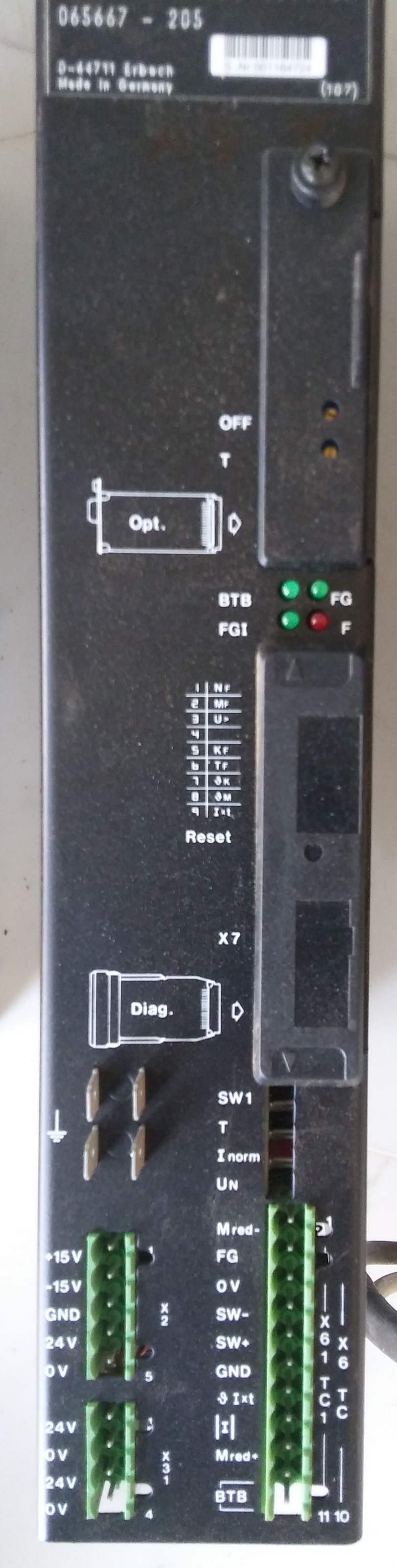
The photos you sent doesn't show the model number of the drives, but they seem to be SM.....T drives. These are Bosch AC servo drive modules.
You need to read the manual in the link above. The drive package consists of a VM power supply module, one SM module for each servo motor and a KM module. There is also an optional EB module that can be added.
The VM module is the DC power supply (DC Link) which is connected to the mains 3 phase supply , usually with inrush current resistors and two contactors. This supplies the SM and the KM (Capacitor) modules with approx. 520V DC power. Without the VM and KM modules you don't have a complete drive system. There are connectors on each of these modules for a communication/monitoring cable that connects them all.
Each of the motors should have three power connections, normally marked U,V and W. These are connected to the very top of each SM module. There must also be an Earth wire. The motors are also fitted with a ROD encoder that connects to the bottom of the SM module. This is for the internal PI loop of the drives (I don't think any output is provided from this encoder for external use so you would probably need additional feedback.)
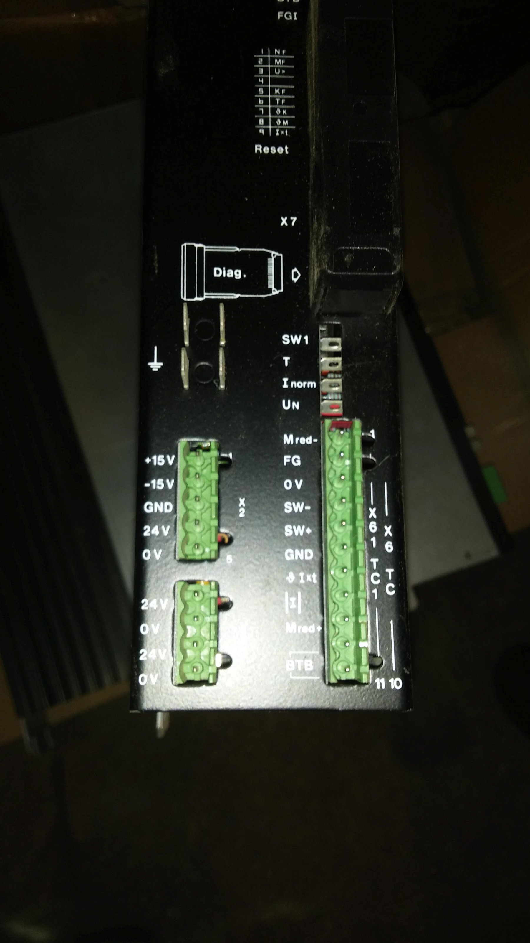
The enable signal is 24V on pins 0V and FG and the analog control voltage must be connected to SW+ and SW-. You need to check in the manual but I think you need to supply 24V to the drive as well.
Henk
The photos you sent doesn't show the model number of the drives, but they seem to be SM.....T drives. These are Bosch AC servo drive modules.
You need to read the manual in the link above. The drive package consists of a VM power supply module, one SM module for each servo motor and a KM module. There is also an optional EB module that can be added.
The VM module is the DC power supply (DC Link) which is connected to the mains 3 phase supply , usually with inrush current resistors and two contactors. This supplies the SM and the KM (Capacitor) modules with approx. 520V DC power. Without the VM and KM modules you don't have a complete drive system. There are connectors on each of these modules for a communication/monitoring cable that connects them all.
Each of the motors should have three power connections, normally marked U,V and W. These are connected to the very top of each SM module. There must also be an Earth wire. The motors are also fitted with a ROD encoder that connects to the bottom of the SM module. This is for the internal PI loop of the drives (I don't think any output is provided from this encoder for external use so you would probably need additional feedback.)
The enable signal is 24V on pins 0V and FG and the analog control voltage must be connected to SW+ and SW-. You need to check in the manual but I think you need to supply 24V to the drive as well.
Henk
Please Log in or Create an account to join the conversation.
21 Apr 2017 05:28 #91746
by Yannis
Replied by Yannis on topic HELP WITH BOSCH ANALOG DC SERVOS
Hi
thanks for the answer
tonight i will take some some photos from the actual attempt of connection on the bench
Note that i m trying to connect only the one motor for test
regards
Yannis
thanks for the answer
tonight i will take some some photos from the actual attempt of connection on the bench
Note that i m trying to connect only the one motor for test
regards
Yannis
Please Log in or Create an account to join the conversation.
23 Apr 2017 11:43 #91879
by Yannis
Replied by Yannis on topic HELP WITH BOSCH ANALOG DC SERVOS
Hi Henk
this is the photo of the connections
waiting for your comments
this is the photo of the connections
waiting for your comments
Please Log in or Create an account to join the conversation.
Time to create page: 0.183 seconds