Allow infinite acceleration/speed on one axis
- Todd Zuercher
-

- Away
- Platinum Member
-

Less
More
- Posts: 4963
- Thank you received: 1369
20 Jan 2017 15:33 #86256
by Todd Zuercher
Replied by Todd Zuercher on topic Allow infinite acceleration/speed on one axis
Could you try riposting the G-code file. It didn't come through.
For Halscope, you have to set a signal source as the trigger, then set the trigger level to something appropriate.
linuxcnc.org/docs/html/hal/tutorial.html#_triggering
At 420mm/min (7mm/sec) you should be good down to about 0.007mm resolution. I think the key to what might be wrong may lie in your g-code.
Please Log in or Create an account to join the conversation.
- Stunning_Rob
-

- Offline
- Junior Member
-

Less
More
- Posts: 21
- Thank you received: 1
20 Jan 2017 15:57 #86257
by Stunning_Rob
Replied by Stunning_Rob on topic Allow infinite acceleration/speed on one axis
Todd,
For the g-code, I started with my base file I'd been testing with before and slowly adjusted it from there (mostly removing every other line of code to double the distance until I started to need more lines of code so that it would adjust the M67 values a bit more (because to many lines of code had been deleted).
Posted here, thanks for taking a look.
Please Log in or Create an account to join the conversation.
- Todd Zuercher
-
- Away
- Platinum Member
-
Less
More
- Posts: 4963
- Thank you received: 1369
20 Jan 2017 15:58 #86258
by Todd Zuercher
Replied by Todd Zuercher on topic Allow infinite acceleration/speed on one axis
On a slightly unrelated note, when I was testing I noticed that the behavior of M67 was not as I expected from the description in the doccumentation. When I had an M67 command on the same line as a commanded move, I would have expected the M67 command to be executed at the end of that move or the start of the next (or maybe the value of the output is interpolated through the duration of the move), but what actually happens is that M67 is activated at the beginning of the move in the line commanded. So if the machine is a X0 and G1X1M67E1Q0 is commanded, the output is set to 1 and the machine BEGINS the move to X1.
sois the same asand that is not the same as this, which gives the result I would have expected from the 2nd bit of code.
so
G0X0
M67E1Q0
G1X1
G1X2G0X0
G1X1M67E1Q0
G1X2G0X0
G1X1
M67E1Q0
G1X2Please Log in or Create an account to join the conversation.
- Stunning_Rob
-
- Offline
- Junior Member
-
Less
More
- Posts: 21
- Thank you received: 1
20 Jan 2017 16:03 #86260
by Stunning_Rob
Replied by Stunning_Rob on topic Allow infinite acceleration/speed on one axis
I was going to look into this after sorting through the velocity problem, but it seems you had the same question as me. (When exactly the M67 command is implemented?) To keep it easier to read/follow I'll probably adjust my script to set the M67 command one line before the movement line, so that the two are never on the same line, to help avoid confusion.
Probably as your first example:
M67 E## Q###
G1 X## Y##
etc
Probably as your first example:
M67 E## Q###
G1 X## Y##
etc
Please Log in or Create an account to join the conversation.
- tommylight
-

- Online
- Moderator
-

Less
More
- Posts: 17809
- Thank you received: 5924
20 Jan 2017 18:38 #86270
by tommylight
Replied by tommylight on topic Allow infinite acceleration/speed on one axis
Here is a file i did, but i had to cut it since it was 2.1MB.
Give it a try, although i use the 0-1 value for the PWM. At least you can see if you get smooth movement.
Give it a try, although i use the 0-1 value for the PWM. At least you can see if you get smooth movement.
Please Log in or Create an account to join the conversation.
- Stunning_Rob
-
- Offline
- Junior Member
-
Less
More
- Posts: 21
- Thank you received: 1
20 Jan 2017 19:56 #86281
by Stunning_Rob
Replied by Stunning_Rob on topic Allow infinite acceleration/speed on one axis
Tommy,
Thanks for the file, I'll run it this evening and see how it goes. Will report back with an update.
Thanks for the file, I'll run it this evening and see how it goes. Will report back with an update.
Please Log in or Create an account to join the conversation.
- tommylight
-
- Online
- Moderator
-
Less
More
- Posts: 17809
- Thank you received: 5924
20 Jan 2017 19:59 #86282
by tommylight
Replied by tommylight on topic Allow infinite acceleration/speed on one axis
You are welcomed, always.
Please Log in or Create an account to join the conversation.
- Todd Zuercher
-
- Away
- Platinum Member
-
Less
More
- Posts: 4963
- Thank you received: 1369
20 Jan 2017 21:23 #86292
by Todd Zuercher
Replied by Todd Zuercher on topic Allow infinite acceleration/speed on one axis
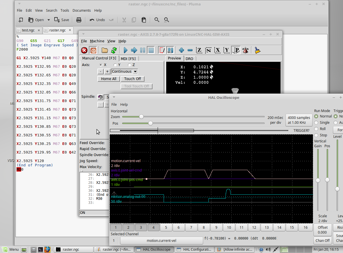
Rob, your 0.3mm test g-code runs fine in my simulation at up to about F3000. Looking like the fault may lie in your machine configuration.
A quick glance at your ini file shows that your max velocity is set to 7mm/s and the acceleration is only 5mm/s~2. Both seem rather lethargic to my eye. (I am used to seeing numbers 10-30 times those or more) Are you sure that your machine has to move that slowly?
But I kind of doubt that is the real source of the problem.
Please Log in or Create an account to join the conversation.
- Todd Zuercher
-
- Away
- Platinum Member
-
Less
More
- Posts: 4963
- Thank you received: 1369
20 Jan 2017 21:25 #86294
by Todd Zuercher
Replied by Todd Zuercher on topic Allow infinite acceleration/speed on one axis
Here is a halscope shot of your test file ran in the sim.
Please Log in or Create an account to join the conversation.
- Stunning_Rob
-
- Offline
- Junior Member
-
Less
More
- Posts: 21
- Thank you received: 1
20 Jan 2017 22:05 #86300
by Stunning_Rob
Replied by Stunning_Rob on topic Allow infinite acceleration/speed on one axis
Todd,
I'm just a small time hobby machinist making things out of wood for friends and family. I used to run faster ('faster' for me anyway....maybe 1,500mm/min and increased accelerations to match) but I kept ruining bearings on my X axis. I chalked this up to the weight of the Z-Axis riding on the X-axis rails, and that the larger forces imposed by the increased acceleration were probably causing 'some' amount of damage. How much I'm not sure, but I can run my little machine about a year between bearing changes when using a max around 420mm/min but I start getting (what I call) "bearing drag" after about 2 months at the higher speeds. The plastic at the ends of the bearings starts tearing apart, so that when moving in one direction the bits of plastic would ride up into the bearing, then when moving the other direction the axis had to overcome the force to get past it and the axis would 'jump' about 1mm resulting in all kinds of horrible looking things any time the axis reversed direction. Long story short, for my poor man's machining budget it doesn't bother me if it takes 10x as long to finish something, my machine utilization rate is probably about 5% over the course of a year anyway. But not to worry -> I'm saving up my pennies for one of these fancy metal milling machines with those (crazy!) velocity rates. I will be there one day...
Anyway, back to our discussion:
Will it tell you what the velocity is dropping to when it executes that 2nd y-move code (with Q20)? I see a sharp point there where it looks like velocity drops considerably and then shoots back up. Based on the rest of the graph that looks like the v=0 point. If that is actually what's happening in your simulator then that would be somewhat similar to how mine keeps dropping off somewhat near the same point.
If I was good with halscope we could probably figure out if they were dropping off at precisely the same time. The remainder of the difference in your velocity graph and mine could then be summed up in acceleration rates most likely. My graph takes the long slow journey towards velocity = 0 because my acceleration values are so low. In your simulated mode your accel values are probably >>> greater than mine, hence the reason yours can drop to zero and recover within such a short time.
It could be my eyes playing tricks on me, but your graph appears to follow the same acceleration rate (linear velocity increase) during "movement start" and the quick (what I am calling) v=0 point of your graph, although the deceleration rate at the v=0 point is not the same as your ending deceleration rate; potentially interesting but for another discussion.
Please Log in or Create an account to join the conversation.
Time to create page: 0.396 seconds