Help with pinout. 2 motors (joints) on one axis. 2.8
18 Jul 2017 13:49 #95978
by joel0407
Help with pinout. 2 motors (joints) on one axis. 2.8 was created by joel0407
A bit of a disclaimer here. I'm at work and reading the manual so I don't have the INI or HAL files here.
"8.8.3.1 Standard Pinout HAL" says:
# finally connect physical pins to the signals
net Xstep => parport.0.pin-03-out
net Xdir => parport.0.pin-02-out
net Ystep => parport.0.pin-05-out
net Ydir => parport.0.pin-04-out
net Zstep => parport.0.pin-07-out
net Zdir => parport.0.pin-06-out
That's great. I understand I want both motors to move the same number of steps so I would just create a second pair of pins and repeat Xstep and Xdir.
But what about homing? I can create separate pins tied to joints for homing sensors. So how does LinuxCNC know which X motor to stop when which Joint homing pin is tripped?
I might have an idea of an answer to this but need confirmation.
I have been told by "rodw" (thanks rod) in another thread that I will need to add:
Joint 0 = X
Joint 1 = X1 (not really an X1, just part of X)
Joint 2 = Y
Joint 3 = Z
to the INI file.
I'm going to suspect that I'll be assigning X1step and X1dir to a pair of pins and not just 2 lots of Xstep and Xdir. I just can't find this in the manual.
Happy Days.
Please Log in or Create an account to join the conversation.
18 Jul 2017 13:56 #95979
by joel0407
Replied by joel0407 on topic Help with pinout. 2 motors (joints) on one axis. 2.8
Sorry guys. I get a bit ahead of myself. I should have said. My machine will be XXYZ machine. 2 steppers on the X axis and 1 each on Y and Z.
Please Log in or Create an account to join the conversation.
- Todd Zuercher
-

- Away
- Platinum Member
-

Less
More
- Posts: 4963
- Thank you received: 1369
18 Jul 2017 15:11 #95984
by Todd Zuercher
Replied by Todd Zuercher on topic Help with pinout. 2 motors (joints) on one axis. 2.8
May I make a suggestion, It might be slightly simpler if you use this joint-axis mapping.
Joint 0 = X
Joint 1 = Y
Joint 2 = Z
Joint 3 = X1 (not really an X1, just part of X)
(not that it really matters a whole lo, but it might make the cut and paste changes you need to make a little simpler.)
Do you have a set config files that you have started working with?
It would be easier if you posted copies of them here as attachments for us to see.
(If you click on Action/Reply rather than Quick Reply, the forum will give you the option of posting attachments.)
Please Log in or Create an account to join the conversation.
18 Jul 2017 15:38 #95985
by joel0407
Replied by joel0407 on topic Help with pinout. 2 motors (joints) on one axis. 2.8
Thanks for the reply Todd,
No I don't have any config files yet. I was reading the manual at work. I've just got home and had a shower. Rode my CT110 to work and it rained. I didn't have my wet weather gear. Off track.\
Will that joint-axis mapping make any difference to the outcome or will it just be easier to cut and paste? I think its more tidy to have the 2, X axis joints together rather than the second one just tacked on the end.
I think I understand the joint-axis linking enough for where I'm up to but I'm struggling to understand the pinout assignment. Having 2 pins assigned to Xstep and 2 pins assigned to Xdir is fine. That to me is no different to physically connecting 2 wires to the was pin though. It as it's not specifying which one is different it doesn't give the software the ability to control each motor separately which is needed for homing.
Please Log in or Create an account to join the conversation.
- Todd Zuercher
-
- Away
- Platinum Member
-
Less
More
- Posts: 4963
- Thank you received: 1369
18 Jul 2017 16:17 #95990
by Todd Zuercher
Replied by Todd Zuercher on topic Help with pinout. 2 motors (joints) on one axis. 2.8
The reason for it being simpler, is because the default axis to joint mapping is x-0, y-1, z-2, a-3, b-4, c-5, u-6, v-7, and w-8. If your second x axis is joint3 rather than joint1, then you only have to redefine one joint rather than 3 of them.
Please Log in or Create an account to join the conversation.
18 Jul 2017 16:19 #95991
by joel0407
Replied by joel0407 on topic Help with pinout. 2 motors (joints) on one axis. 2.8
I think that's a minor thing at this stage unless I have to define them in multiple places.
It's the Parallel Port Pinout I'm struggling with.
It's the Parallel Port Pinout I'm struggling with.
Please Log in or Create an account to join the conversation.
- Todd Zuercher
-
- Away
- Platinum Member
-
Less
More
- Posts: 4963
- Thank you received: 1369
18 Jul 2017 16:33 - 18 Jul 2017 16:37 #95994
by Todd Zuercher
The actual pinout is completely arbitrary. At least as far as what interface pins do what (parallel port pins, other io pins). You need to separate what you are thinking an axis letter X,Y,Z... is from what a motor or degree of freedom aka a joint is. In Linuxcnc they can be the same such as for most trivial kinematic machines (most milling machines), or completely different (most robots). In Linuxcnc the axis letters are for representation of location and movement in the Cartesian space coordinate system. Your Joints are your physical motors and moving parts of your machine.
So the two joints that you are going to assign to the two motors on your X axis of your gantry machine will be controlled separately with different homing switches, and step-generators (or PID loops in the case of servos). They will be commanded identical movements while maintaining the squaring offsets you programed into their homing process when you configured the machine.
Replied by Todd Zuercher on topic Help with pinout. 2 motors (joints) on one axis. 2.8
I think I understand the joint-axis linking enough for where I'm up to but I'm struggling to understand the pinout assignment. Having 2 pins assigned to Xstep and 2 pins assigned to Xdir is fine. That to me is no different to physically connecting 2 wires to the was pin though. It as it's not specifying which one is different it doesn't give the software the ability to control each motor separately which is needed for homing.
The actual pinout is completely arbitrary. At least as far as what interface pins do what (parallel port pins, other io pins). You need to separate what you are thinking an axis letter X,Y,Z... is from what a motor or degree of freedom aka a joint is. In Linuxcnc they can be the same such as for most trivial kinematic machines (most milling machines), or completely different (most robots). In Linuxcnc the axis letters are for representation of location and movement in the Cartesian space coordinate system. Your Joints are your physical motors and moving parts of your machine.
So the two joints that you are going to assign to the two motors on your X axis of your gantry machine will be controlled separately with different homing switches, and step-generators (or PID loops in the case of servos). They will be commanded identical movements while maintaining the squaring offsets you programed into their homing process when you configured the machine.
Last edit: 18 Jul 2017 16:37 by Todd Zuercher.
Please Log in or Create an account to join the conversation.
18 Jul 2017 16:39 #95995
by joel0407
Replied by joel0407 on topic Help with pinout. 2 motors (joints) on one axis. 2.8
Yep, understand that separation of joints (motors) and Axis (Cartesian space). The problem is I can't find that separation in the pinouts.
I have 2 motors on one axis. I need them to move independently to square the gantry should it become out of alignment. To do that I can't send the same signal to 2 different motors otherwise they will both do the same thing. As they home, if one hits the home sensor before the other then I need that motor to stop and the other to continue. That will not happen if I am sending the same signal to both motors. If that was the case then if one stopped then so would the other. If one moved then so would the other.
How do I define the difference.
Please Log in or Create an account to join the conversation.
18 Jul 2017 16:42 #95996
by joel0407
Replied by joel0407 on topic Help with pinout. 2 motors (joints) on one axis. 2.8
This is from "andy pugh" in a similar thread:
"In hardware you can wire the two motors in series (this is probably a bad idea) or parallel (also not a great idea)
In hardware you can take the step-dir wires to two drivers.
In software you can take the step pulses to two different sets of output pins.
in software you can send the motor position to two different step generators.
In software you can send the axis position to two different motor positions."
I want to do option 3 for the software.
Please Log in or Create an account to join the conversation.
18 Jul 2017 16:45 #95998
by joel0407
Replied by joel0407 on topic Help with pinout. 2 motors (joints) on one axis. 2.8
Here is his post:
need some direction on how to configure linuxcnc to run two steppers for y axis,
This is partly because there are a number of different ways to do it.
In hardware you can wire the two motors in series (this is probably a bad idea) or parallel (also not a great idea)
In hardware you can take the step-dir wires to two drivers.
In software you can take the step pulses to two different sets of output pins.
in software you can send the motor position to two different step generators.
In software you can send the axis position to two different motor positions.
The last way is the most sophisticated, and the most difficult to set up, but does allow you to home both sides and auto-square.
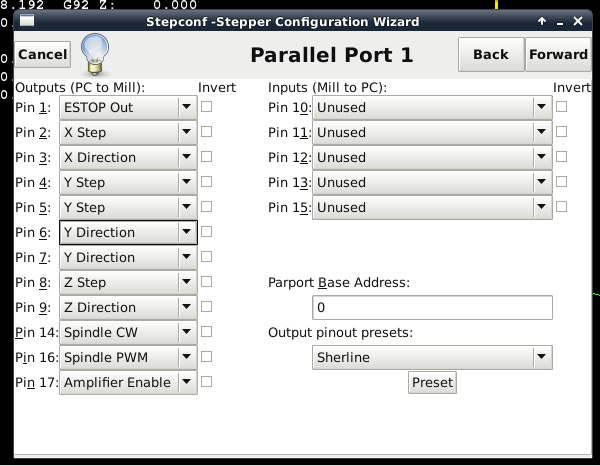
The easiest way (and a way that does not require any hardware changes if you later decide on the last way) is to take the Y-stepgen step/dir signals to two sets of output pins. You can configure that way in Stepconf, see how Ystep and Ydir each go to two pins
Please Log in or Create an account to join the conversation.
Time to create page: 0.169 seconds