Re:Hardinge CHNC 1 Lathe

28 Feb 2010 17:09 #2120
by BigJohnT
Replied by BigJohnT on topic Re:Hardinge CHNC 1 Lathe
Peter,
Thanks, I found some a Digikey...
Thanks
John
Thanks, I found some a Digikey...
Thanks
John
Please Log in or Create an account to join the conversation.
- Kirk_Wallace
- Offline
- Premium Member
-

Less
More
- Posts: 81
- Thank you received: 7
28 Feb 2010 17:28 #2121
by Kirk_Wallace
Replied by Kirk_Wallace on topic Re:Hardinge CHNC 1 Lathe
Someone has been busy. The burnt capacitor (C1) has a polarity like batteries and diodes. The tapered end indicates which way to orient the part. There should be a plus sign on the board showing which way the tapered end goes. It may be that the power was hooked up backwards at one time. Or the capacitor just failed from age. If the power was hooked up backwards, other things could be damaged. Here is an example:
search.digikey.com/scripts/DkSearch/dksu...l&name=718-1431-2-ND
www.vishay.com/doc?40019
Since you have a single chip, it might be this 10 to 4 priority encoder:
search.digikey.com/scripts/DkSearch/dksu...&name=296-14247-5-ND
I remember when IC's were the hot new thing, that only the military could afford. The 10-bit chip probably wasn't available when they made my board.
I believe the silicone seal in the holes, where the cables enter, is not original and was used to try to keep the oil out, but the only way I know to do this is by replacing all of the worn o and x-rings in the turret assembly. I got all but the extra large x-ring that goes around the table skirt from Mcmaster-Carr. I had to buy minimum quantities on some, so I can send you some of my duplicates. The previous owner said he had to replace a good number of seals every few years. Replacing the seals made a big difference in how well the turret works. I'd leave the silicone out so that if any oil gets in, it has a way to get out, and so that venting air has a way to get out with out blowing any seals.
The magnet holder is not indexed to the shaft. I left the screw a little loose to tune the magnets position so that the sensor would trip as early as possible but remain tripped when the table parks. I needed the early trip so that the software and stop mechanism could activate before passing the selected tool position. It's like trying to grab a ring on a carousel, if you miss the ring, you have to keep going around until you get it. I need to add time-outs to the component so that if something goes wrong, the turret won't turn endlessly.
I wrote the turret component because I didn't want to learn ladder logic and it is much more direct. You can use it if you want. Just download it from my website:
www.wallacecompany.com/cnc_lathe/HNC/emc2/turret.comp
You will need to use Synaptic to install emc2-dev (or emc-dev?). Then use the command:
"comp --install turret.comp"
This link covers the command:
www.linuxcnc.org/docview/html//hal_comp.html#r1_12
www.linuxcnc.org/docview/html//hal_comp.html#r1_12
But it looks like a lot has changed from the last time I looked through the documentation. There may a better way to install a comp. When the comp is installed, the new HAL pins show up and can be connected appropriately.
I just remembered the park sensor needs to be added to the turret comp. Currently, the tool-changed signal gets invoked when the stop state is invoked. The park sensor should be checked first before sending tool-changed. Plus the air pressure sensor should be checked too. My problem is that the turret works fine as is, so there is less incentive to complete these features.
--
Kirk Wallace
www.wallacecompany.com/machine_shop/
www.wallacecompany.com/E45/index.html
California, USA
Please Log in or Create an account to join the conversation.
- Kirk_Wallace
- Offline
- Premium Member
-
Less
More
- Posts: 81
- Thank you received: 7
28 Feb 2010 17:44 #2123
by Kirk_Wallace
Replied by Kirk_Wallace on topic Re:Hardinge CHNC 1 Lathe
I forgot to mention, I set the magnet so that the current tool number shows towards the machine front on the carriage. I originally set it to show towards the head stock, which is also the actual tool location, but I found it much easier to check the current tool number if it pointed out towards the operator. I used a Sharpie to number the top of the table for the actual tool positions. In other words, if tool one is current, tool one points towards the headstock, the Sharpie number is towards the headstock, but the table skirt number one points out the front of the machine towards the operator. I could not find anything in my Hardinge documentation that covers how the number should be set, so I just did as I pleased.
--
Kirk Wallace
www.wallacecompany.com/machine_shop/
www.wallacecompany.com/E45/index.html
California, USA
--
Kirk Wallace
www.wallacecompany.com/machine_shop/
www.wallacecompany.com/E45/index.html
California, USA
Please Log in or Create an account to join the conversation.
- Kirk_Wallace
- Offline
- Premium Member
-
Less
More
- Posts: 81
- Thank you received: 7
28 Feb 2010 18:00 - 28 Feb 2010 18:11 #2125
by Kirk_Wallace
Replied by Kirk_Wallace on topic Re:Hardinge CHNC 1 Lathe
Oops, and the Hall sensors are sensitive to the North (or is it South?) end of the magnet, so if you test your sensors with the wrong end, they won't work. Just turn the magnet over and try again, any magnet should do. And don't forget to tighten the magnet down when you have finished tuning the encoder.
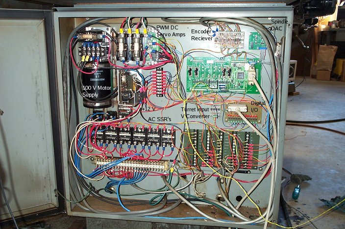
I forget how the chip works, but I think the outputs only sink current, so a pull-up and voltage source is needed. I used 24 Volts and used an opto-isolator to convert to 5 Volts at my controller inputs. The optos are labeled "Turret Input V Converter" here:
(I think the picture gets larger if you click on it)
--
Kirk Wallace
www.wallacecompany.com/machine_shop/
www.wallacecompany.com/E45/index.html
California, USA
Last edit: 28 Feb 2010 18:11 by Kirk_Wallace.
Please Log in or Create an account to join the conversation.
28 Feb 2010 23:46 - 28 Feb 2010 23:50 #2129
by BigJohnT
Replied by BigJohnT on topic Re:Hardinge CHNC 1 Lathe
Kirk,
The chip is marked:
LM324M
W99EQ009
MALAYSIA
The reed switches are marked:
613SS4
429
I would order one of those too if I could cross it over.
Is the output from the turret encoder 24V?
Thanks
John
The chip is marked:
LM324M
W99EQ009
MALAYSIA
The reed switches are marked:
613SS4
429
I would order one of those too if I could cross it over.
Is the output from the turret encoder 24V?
Thanks
John
Last edit: 28 Feb 2010 23:50 by BigJohnT.
Please Log in or Create an account to join the conversation.
- Kirk_Wallace
- Offline
- Premium Member
-
Less
More
- Posts: 81
- Thank you received: 7
01 Mar 2010 00:59 #2130
by Kirk_Wallace
Replied by Kirk_Wallace on topic Re:Hardinge CHNC 1 Lathe
Interesting.
The LM324M <- you sure it's not an N?
www.fairchildsemi.com/ds/LM/LM324.pdf
Looks like Digikey has them:
search.digikey.com/scripts/DkSearch/dksu...ail&name=LM324NFS-ND
Honeywell 613SS4, I could only find this data:
sccatalog.honeywell.com/pdbdownload/imag...s.series.chart.1.pdf
sensing.honeywell.com/index.cfm?ci_id=140301&la_id=1&pn=613SS4
It looks like a more common Hall switch might work, but Mouser seems to have them:
www.mouser.com/ProductDetail/Honeywell/6...EN6YAX7IARveS86oQ%3D
but a newer equivalent would be cheaper.
The 613 looks like it has a 20 Volt max. The LM324 maxes at 32 V.
I am unfamiliar with this circuit, but it might be like the right half of this ADC:

www.opamp-electronics.com/tutorials/digital_theory_ch_013.htm
The Hall sensors would replace the left half and feed the diode array. The diode array would then feed the op-amps which would clean up the array output. A priority encoder chip seems to be much less complex, but you got whatcha got.
To trouble shoot, you can measure resistance across the power leads to see if the power input is shorted. If it is shorted pull suspected parts and test the power pins and replace the shorted chips. Check that the diodes conduct in only one direction with your meter's diode resistance setting (looks like -i<i-). When the power shorts are gone, you can try to power up the board and check that the Hall outputs switch on and off with a magnet. Check that the signals reach the op-amp inputs, then check the outputs.
--
Kirk Wallace
www.wallacecompany.com/machine_shop/
www.wallacecompany.com/E45/index.html
California, USA
The LM324M <- you sure it's not an N?
www.fairchildsemi.com/ds/LM/LM324.pdf
Looks like Digikey has them:
search.digikey.com/scripts/DkSearch/dksu...ail&name=LM324NFS-ND
Honeywell 613SS4, I could only find this data:
sccatalog.honeywell.com/pdbdownload/imag...s.series.chart.1.pdf
sensing.honeywell.com/index.cfm?ci_id=140301&la_id=1&pn=613SS4
It looks like a more common Hall switch might work, but Mouser seems to have them:
www.mouser.com/ProductDetail/Honeywell/6...EN6YAX7IARveS86oQ%3D
but a newer equivalent would be cheaper.
The 613 looks like it has a 20 Volt max. The LM324 maxes at 32 V.
I am unfamiliar with this circuit, but it might be like the right half of this ADC:
www.opamp-electronics.com/tutorials/digital_theory_ch_013.htm
The Hall sensors would replace the left half and feed the diode array. The diode array would then feed the op-amps which would clean up the array output. A priority encoder chip seems to be much less complex, but you got whatcha got.
To trouble shoot, you can measure resistance across the power leads to see if the power input is shorted. If it is shorted pull suspected parts and test the power pins and replace the shorted chips. Check that the diodes conduct in only one direction with your meter's diode resistance setting (looks like -i<i-). When the power shorts are gone, you can try to power up the board and check that the Hall outputs switch on and off with a magnet. Check that the signals reach the op-amp inputs, then check the outputs.
--
Kirk Wallace
www.wallacecompany.com/machine_shop/
www.wallacecompany.com/E45/index.html
California, USA
Please Log in or Create an account to join the conversation.
01 Mar 2010 14:04 - 01 Mar 2010 14:05 #2138
by BigJohnT
Replied by BigJohnT on topic Re:Hardinge CHNC 1 Lathe
Kirk,
I didn't read it with enough light or glasses on LOL, yes it is LM324N.
From reading the data sheet it looks like the output is 28 volts? If that is correct then I can use the output's directly to my 7i37 inputs?
I'm trying as best as I can to gather my info before I place an order with Digikey.
Do you have a part number for a newer equivalent hall switch?
Thanks so much for your help.
John
Last edit: 01 Mar 2010 14:05 by BigJohnT.
Please Log in or Create an account to join the conversation.
- Kirk_Wallace
- Offline
- Premium Member
-
Less
More
- Posts: 81
- Thank you received: 7
01 Mar 2010 21:15 #2144
by Kirk_Wallace
Replied by Kirk_Wallace on topic Re:Hardinge CHNC 1 Lathe
I think the 613SS4 max is 20 Volts, and if the Tantalum capacitor is rated 24 Volts, usually the circuit is run way under the maximum in order to have a safety margin. I would guess your encoder board is meant to run with 12 Volts.
The 7i37 looks like it will take up to 24 Volts. You should check with Peter (from Mesa) to make sure but I think the inputs are just like a 4.4k Ohm resistor and an LED in series. Sorta like this:
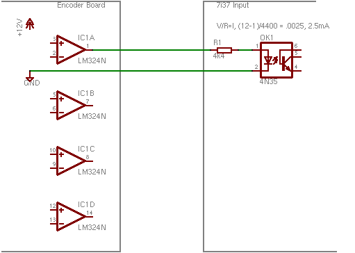
(Click on image for lager version)
You need two wires for each encoder output. One to supply the signal, another to complete the circuit to the encoder board's ground.
I would think that you could do a lot of testing before ordering parts. It may be the burnt capacitor is the only bad part. I'll need to do a little more research to find an equivalent for the 613SS4.
--
Kirk Wallace
www.wallacecompany.com/machine_shop/
www.wallacecompany.com/E45/index.html
California, USA
The 7i37 looks like it will take up to 24 Volts. You should check with Peter (from Mesa) to make sure but I think the inputs are just like a 4.4k Ohm resistor and an LED in series. Sorta like this:
(Click on image for lager version)
You need two wires for each encoder output. One to supply the signal, another to complete the circuit to the encoder board's ground.
I would think that you could do a lot of testing before ordering parts. It may be the burnt capacitor is the only bad part. I'll need to do a little more research to find an equivalent for the 613SS4.
--
Kirk Wallace
www.wallacecompany.com/machine_shop/
www.wallacecompany.com/E45/index.html
California, USA
Please Log in or Create an account to join the conversation.
03 Mar 2010 00:42 - 03 Mar 2010 23:35 #2158
by BigJohnT
Replied by BigJohnT on topic Re:Hardinge CHNC 1 Lathe
While pondering what parts to order for the turret I moved on to the spindle. I can get it to go forward with M4 and backward with M3. The output of the 7i33 is reversed of what I'd expect. AOUT2 is -v for M3 and +v for M4. If I reverse the wires then both M3 and M4 go backwards. If I invert IO Pin 019 (P2-39): PWMGen #2, pin Out0 (PWM or Up) (Output) it runs at about 4 times as fast as commaned. If I invert IO Pin 020 (P2-39): PWMGen #2, pin Out1 (PWM or Up) (Output) nothing changes. The drive is a Fanuc digital AC spindle servo drive A06B-6055-H106 if that helps.
I got it fingered out I had to reverse the scale to get it to turn the right way. I'll see if I can make some kind of diagram on this...
Thanks
John
I got it fingered out I had to reverse the scale to get it to turn the right way. I'll see if I can make some kind of diagram on this...
Thanks
John
Last edit: 03 Mar 2010 23:35 by BigJohnT. Reason: don't know which drive is which I guess
Please Log in or Create an account to join the conversation.
- Kirk_Wallace
- Offline
- Premium Member
-
Less
More
- Posts: 81
- Thank you received: 7
03 Mar 2010 02:42 #2160
by Kirk_Wallace
Replied by Kirk_Wallace on topic Re:Hardinge CHNC 1 Lathe
I'm glad you got your spindle going. I don't have a clue about that kind of drive.
I looked at your Hall sensor again. Your sensor has two output pins. My guess is that only one is used, but I don't know for sure. Another option would be to make a new board similar to mine. The circuit is much less complicated, but you would need to fabricate a pcb to mount the sensors and wiring on. I can make up a schematic. The electronic parts would be around $15.
Here is Vince's encoder:
www.cnczone.com/forums/showthread.php?t=50685&page=13
I don't think he even uses an encoder chip. I believe the sensors go to a PLC.
--
Kirk Wallace
www.wallacecompany.com/machine_shop/
www.wallacecompany.com/E45/index.html
California, USA
Please Log in or Create an account to join the conversation.
Moderators: cncbasher
Time to create page: 0.110 seconds