

- Posts: 116
- Thank you received: 0
Void Lock Kerf Crossing suggestion
6 years 11 months ago #151325
by EW_CNC
Void Lock Kerf Crossing suggestion was created by EW_CNC
I am using void lock with a fair amount of success when cutting steel 3/8" and thinner. Thicker steel is not as good.
I have the void override setting at 500%.
I realize void lock is still not perfected, but it is definitely a good start.
One problem I experience with it is when the torch comes to a corner, velocity lock comes on and also void lock comes on, then void lock sometimes doesn't turn off again. I believe what is happening is, when torch gap keeps increasing after coming out of the corner, it will not cancel void lock until it comes into range again so that the THC can control it again. Sometimes void lock will stay on for a long time before it gets in range again, or till the end of the part. It's mostly a problem if the torch changes direction when it is at a high spot on the sheet caused by warpage or variation in table height. My question would be, is it possible to have a maximum set amount of time or distance that void lock could be active? ( 2-3 seconds or .5 - 1" travel distance). It would need to turn off and allow enough time for the THC to correct itself before it would be active again. Most of my void lock is needed only for a very short time and it is spaced apart on the sheet. What are others experiencing when using void lock?
E.W.
Please Log in to join the conversation.

6 years 11 months ago #151326
by phillc54
Replied by phillc54 on topic Void Lock Kerf Crossing suggestion
Thanks for the report, I have been pretending void lock doesn't exist. 
Would it be better if void lock was disabled if velocity lock was active?
Would it be better if void lock was disabled if velocity lock was active?
Please Log in to join the conversation.
6 years 11 months ago #151330
by EW_CNC
Replied by EW_CNC on topic Void Lock Kerf Crossing suggestion
Yes, that might take care of the problem.
If the torch is up to speed and velocity lock turns off, would the torch voltage be within range to keep void lock from activating?
If the torch is up to speed and velocity lock turns off, would the torch voltage be within range to keep void lock from activating?
Please Log in to join the conversation.
6 years 11 months ago #151331
by phillc54
Replied by phillc54 on topic Void Lock Kerf Crossing suggestion
I am pretty sure it will be ok, I will take a look later and see what I can do.
Please Log in to join the conversation.
6 years 11 months ago #151402
by phillc54
Replied by phillc54 on topic Void Lock Kerf Crossing suggestion
If you are happy to compile the PlacmaC component and experiment a bit I have made a few changes to try.
In the bench testing I did, I found that I needed to increase the Void Override Percentage to something like 3000. It seems to be a bit dependant on the THC Threshold so I have also changed plasmac_config.py so it allows a high Void Override Percentage of 10000. Because of this I am a bit hesitant to push it yet in case it breaks any existing configs.
It is only suitable at this stage for anyone who would like to experiment.
Copy both attached files into your home directory then open a terminal and follow your LinuxCNC installation type.
Buildbot:
Run In Place:
If it goes pear shaped then rename plasmac.so.old back to plasmac.so
In the bench testing I did, I found that I needed to increase the Void Override Percentage to something like 3000. It seems to be a bit dependant on the THC Threshold so I have also changed plasmac_config.py so it allows a high Void Override Percentage of 10000. Because of this I am a bit hesitant to push it yet in case it breaks any existing configs.
It is only suitable at this stage for anyone who would like to experiment.
Copy both attached files into your home directory then open a terminal and follow your LinuxCNC installation type.
Buildbot:
Code:
sudo cp plasmac_config.py /usr/share/doc/linuxcnc/examples/sample-configs/by_machine/plasmac/
sudo mv /usr/lib/linuxcnc/modules/plasmac.so /usr/lib/linuxcnc/modules/plasmac.so.old
sudo halcompile --install plasmac.comp
Run In Place:
Code:
cp plasmac_config.py /usr/share/doc/linuxcnc/examples/sample-configs/by_machine/plasmac/
mv linuxcnc-dev/rtlib/plasmac.so linuxcnc/rtlib/plasmac.so.old
source ./linuxcnc-dev/scripts/rip-environment
halcompile --install plasmac.comp
If it goes pear shaped then rename plasmac.so.old back to plasmac.so
Please Log in to join the conversation.
6 years 11 months ago #151488
by rodw
Replied by rodw on topic Void Lock Kerf Crossing suggestion
I have to chime in here and suggest that in my testing, I don't think Plasmac is following a good void crossing algorithm. I have started on that but have not had any time for a very long time to continue the experiments I was doing with my separate void crossing component. I think there is some discussion in the plasma primer in the docs.
Please Log in to join the conversation.
6 years 11 months ago #151616
by EW_CNC
Replied by EW_CNC on topic Void Lock Kerf Crossing suggestion
I did some sample cutting on 3/16 thick steel.
I set the void lock percentage at 3000, it did not activate void lock.
Next I set it at 30 it seemed overly sensitive. With the setting at 100 I did some kerf crossings. Void lock activated and I had no downward motion of the torch. I will do more experimenting later to see if I have consistent results.
Phillc,
Rodw,
I set the void lock percentage at 3000, it did not activate void lock.
Next I set it at 30 it seemed overly sensitive. With the setting at 100 I did some kerf crossings. Void lock activated and I had no downward motion of the torch. I will do more experimenting later to see if I have consistent results.
Phillc,
Yes, it might not be perfect, but it is sure better than nothing. Thanks!Thanks for the report, I have been pretending void lock doesn't exist.
Rodw,
Do you think it can be improved to were we have more consistent results while cutting different steel thickness and feed rates?I have to chime in here and suggest that in my testing, I don't think Plasmac is following a good void crossing algorithm.
Please Log in to join the conversation.
6 years 10 months ago #151630
by rodw
Replied by rodw on topic Void Lock Kerf Crossing suggestion
YEs, I believe there is a better way and it covered at a high level in the plasma primer
linuxcnc.org/docs/devel/html/plasma/plas...k_velocity_anti_dive
The graph was plotted from 16000 readings in halscope.
The attached component is designed to decode the thcad voltage outside of Plasmac and it also has code to calculate a moving average (the red line in the primer). But I am not sure how many readings to average (is it 10 or is it 100 or some other number)
The theory is that the rate of change when passing a void is orders of magnitude higher than it is when dealing with normal warpage.
The first step is to use halscope and plot dv/dt during normal cutting. Then the next step is to set a threshold just above it. I have a feeling from memory normal cutting was around 1000 so the threshold should be around 1500-3000.
But I really think the first step is to gather and plot data in halsope before setting the threshold.
Sorry but I am off to China for a week, See how you go in my absence. Get Phill to tell you where to connect the pin void-hold to disable THC if you can come up with a proposed threshold.
I'm not sure if the method to re-enable the THC is correct after you get to the end of the void but it seems reasonable.
I've put an enormous effort to get this far and I think we are on the right track.
linuxcnc.org/docs/devel/html/plasma/plas...k_velocity_anti_dive
The graph was plotted from 16000 readings in halscope.
The attached component is designed to decode the thcad voltage outside of Plasmac and it also has code to calculate a moving average (the red line in the primer). But I am not sure how many readings to average (is it 10 or is it 100 or some other number)
The theory is that the rate of change when passing a void is orders of magnitude higher than it is when dealing with normal warpage.
The first step is to use halscope and plot dv/dt during normal cutting. Then the next step is to set a threshold just above it. I have a feeling from memory normal cutting was around 1000 so the threshold should be around 1500-3000.
But I really think the first step is to gather and plot data in halsope before setting the threshold.
Sorry but I am off to China for a week, See how you go in my absence. Get Phill to tell you where to connect the pin void-hold to disable THC if you can come up with a proposed threshold.
I'm not sure if the method to re-enable the THC is correct after you get to the end of the void but it seems reasonable.
Attachment not found
I've put an enormous effort to get this far and I think we are on the right track.
Please Log in to join the conversation.
6 years 10 months ago #151632
by rodw
Replied by rodw on topic Void Lock Kerf Crossing suggestion
Just some explanatory notes on this,
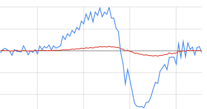
The dv/dt osculates during normal cutting around the average torch volts so the threshold should be set just above the blue line during normal cuting. you also need to overlay torch voltage on this to get better clarity, but I think the first sharp peak is probably at the edge of the hole and then the arc gets dragged along for a bit until it can' hang on any further and the arc voltage shoots way high maybe by 30-50 volts.
SO the threshold needs to be just above the positive blue line. I suspect even if that first sharp peak crossed the threshold it would still be OK as that is probably the edge of the material
I will say it is very hard to get your head around the plots as you are plotting a derived value.
Please Log in to join the conversation.
6 years 6 months ago #165191
by rodw
Replied by rodw on topic Void Lock Kerf Crossing suggestion
Well its been a long time coming but it looks like I have finally nailed Void crossing sensing on the last cut for the day! So now I just need Phill to add a pin to Plasmac to disable the THC and I can tidy this up and share the feature
This is 2mm mild steel with a cut crossing 4 perpendicular cuts 10mm apart
Red = Torch Voltage
Green = dv/dt (change in voltage over time)
White = Void crossing output pin to disable THC.
I was just gobsmacked when I saw that plot unfold before my eyes!
The gradual slope up on the torch voltage is becasue there is no THC enabled during these test cuts. I expect once the THC is in play and controlling torch height, we will have perfect results! Well I hope we catch the void fast enough for that anyway! It looks like we do.
Also need to test on different thicknesses.
This is 2mm mild steel with a cut crossing 4 perpendicular cuts 10mm apart
Attachment not found
Red = Torch Voltage
Green = dv/dt (change in voltage over time)
White = Void crossing output pin to disable THC.
I was just gobsmacked when I saw that plot unfold before my eyes!
The gradual slope up on the torch voltage is becasue there is no THC enabled during these test cuts. I expect once the THC is in play and controlling torch height, we will have perfect results! Well I hope we catch the void fast enough for that anyway! It looks like we do.
Also need to test on different thicknesses.
Please Log in to join the conversation.
Time to create page: 0.099 seconds