- Other Stuff
- Show Your Stuff
- 2+2+3 More Plasma builds, double the joy ! 3X2M and 2.5X1.5M cnc plasma build.
2+2+3 More Plasma builds, double the joy ! 3X2M and 2.5X1.5M cnc plasma build.
- tommylight
-
 Topic Author
- Online
- Moderator
-

Less
More
- Posts: 17782
- Thank you received: 5909
28 Apr 2020 08:39 #165923
by tommylight
-
BTW, Lam do make stepper drives with encoder feedback and there was one type on sale at mechapro.de
www.mechapro.de/shop/Stepper-motor-drive...286.html?language=en
www.mechapro.de/pdf/DDS1_Flyer_EN.pdf
That one is very reasonable considering the quality is very high, i could not kill a DS1044 on purpose even by reversing the power supply or shorting motor wires to anything.
Replied by tommylight on topic 2+2+3 More Plasma builds, double the joy ! 3X2M and 2.5X1.5M cnc plasma build.
From what i have used regarding stepper drives, These are the only ones that would justify putting encoders on motors and closing the loop in Linuxcnc as the have an input that says BOOST !!! That can be used to be activates the instance the step count sent from stepgen does not match the steps from the encoder so it will add more current to the motor giving the motor a better chance at catching up. Be aware that by default that boost pin is reversed, so active high will drop the current, can be changed with the software and the usb programmer for it.Tommy, thanks. I also see that they have steppers listed there with encoders but Lam don't list them on their own site. NOr do they have drivers with encoder inputs I can see. So would you close the feedback in Linuxcnc if You went that way?
-
That seems all good, and with that reduction it will be also usable as a router for sure. I did try to surf the gantry yesterday at 10m/m for over 10 minutes i was jumping on it, and they never stalled. That is with Nema 23 motors at 1.8A, 1:3 reduction and a 15 tooth 3mm pitch pulley, so 15mm per revolution of the motor, or ideal for plasma cutting.I was kinda thinking 4 NEMA 23's at around 260 oz/in 3 amps (say Lams M1233051), DS1076 drivers, 70-80 volts with 5:1 reduction drives on a rack and pinion drives should smash a light (say 30kg) gantry
And probably also do the same with a DS1044 on a 48 v SMPS
What do you think?
Or should I use a Toroidal and Lam's power supply modules?
BTW, Lam do make stepper drives with encoder feedback and there was one type on sale at mechapro.de
www.mechapro.de/shop/Stepper-motor-drive...286.html?language=en
www.mechapro.de/pdf/DDS1_Flyer_EN.pdf
That one is very reasonable considering the quality is very high, i could not kill a DS1044 on purpose even by reversing the power supply or shorting motor wires to anything.
The following user(s) said Thank You: Coachbuilder
Please Log in or Create an account to join the conversation.
- tommylight
-
Topic Author
- Online
- Moderator
-
Less
More
- Posts: 17782
- Thank you received: 5909
28 Apr 2020 21:41 #166013
by tommylight
Replied by tommylight on topic 2+2+3 More Plasma builds, double the joy ! 3X2M and 2.5X1.5M cnc plasma build.
The Z's are coming, the Z's are coming ! ")

Attachments:
Please Log in or Create an account to join the conversation.
- tommylight
-
Topic Author
- Online
- Moderator
-
Less
More
- Posts: 17782
- Thank you received: 5909
29 Apr 2020 00:53 #166043
by tommylight
Replied by tommylight on topic 2+2+3 More Plasma builds, double the joy ! 3X2M and 2.5X1.5M cnc plasma build.
And tandem Y axis are finished on both machines !
Looong day, it is 2:50AM, so in a bit i will be chasing some dreams, but i doubt i catch anything, i dream about once a year.
Here is a short video of both axis moving at 15m/m, or "breaking them in" as car guys would say.
Enjoy, and thank you all.
Regards,
Tom.
Looong day, it is 2:50AM, so in a bit i will be chasing some dreams, but i doubt i catch anything, i dream about once a year.
Here is a short video of both axis moving at 15m/m, or "breaking them in" as car guys would say.
Enjoy, and thank you all.
Regards,
Tom.
Please Log in or Create an account to join the conversation.
- tommylight
-
Topic Author
- Online
- Moderator
-
Less
More
- Posts: 17782
- Thank you received: 5909
30 Apr 2020 16:23 #166228
by tommylight
Replied by tommylight on topic 2+2+3 More Plasma builds, double the joy ! 3X2M and 2.5X1.5M cnc plasma build.
This was tough, i sure know how to complicate everything !
This is the final implementation of the Z axis, after many, many others i tried and discarded them for being to heavy/bulky/ugly. :
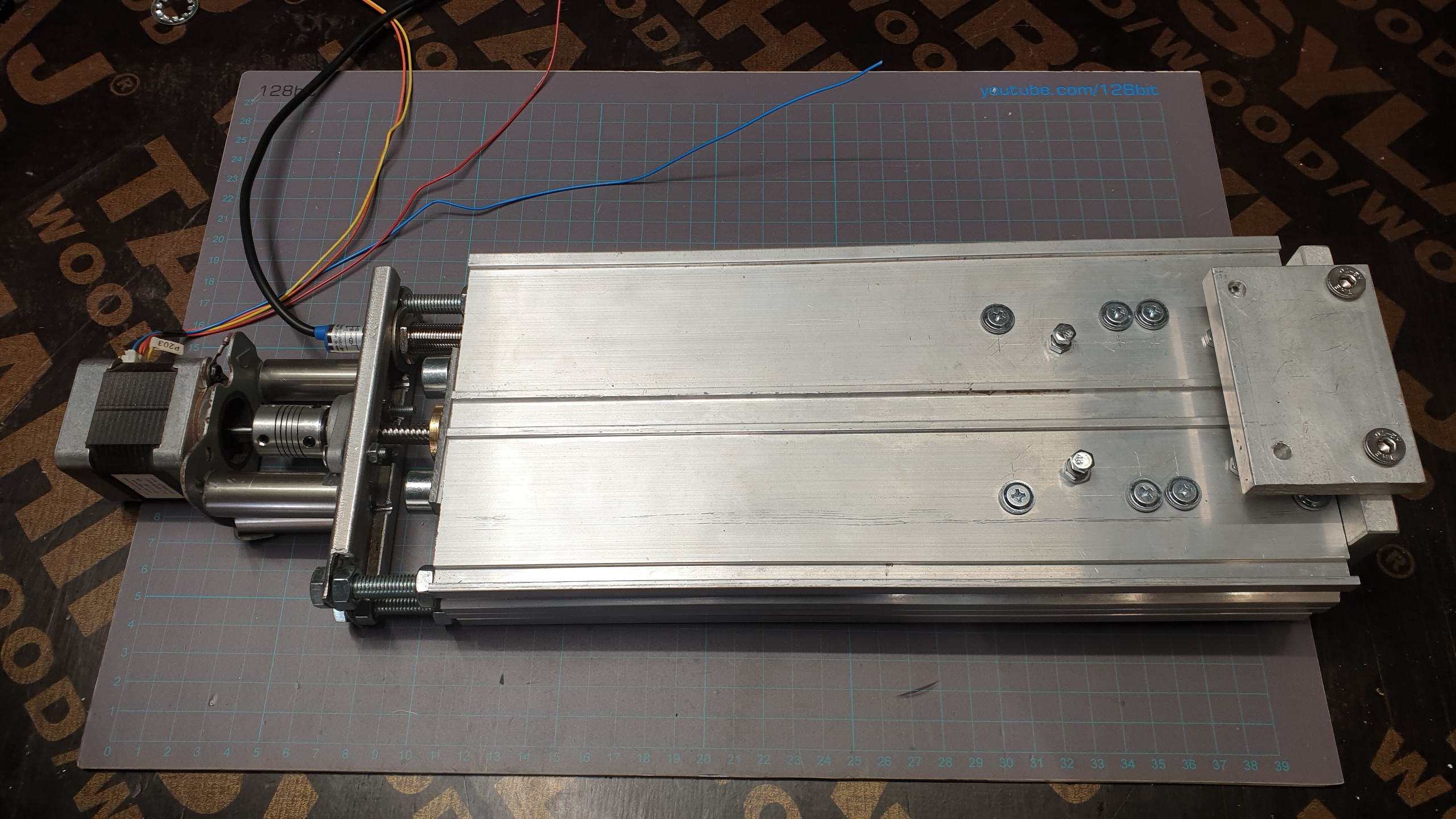
The profile is 28.5cm long and 34mm wide inside so not much space there for all the stuff that i had to put inside
Travel is 165mm, screw can do 220mm, but the bearing took 100mm inside, so i got left with only 185mm to work with.
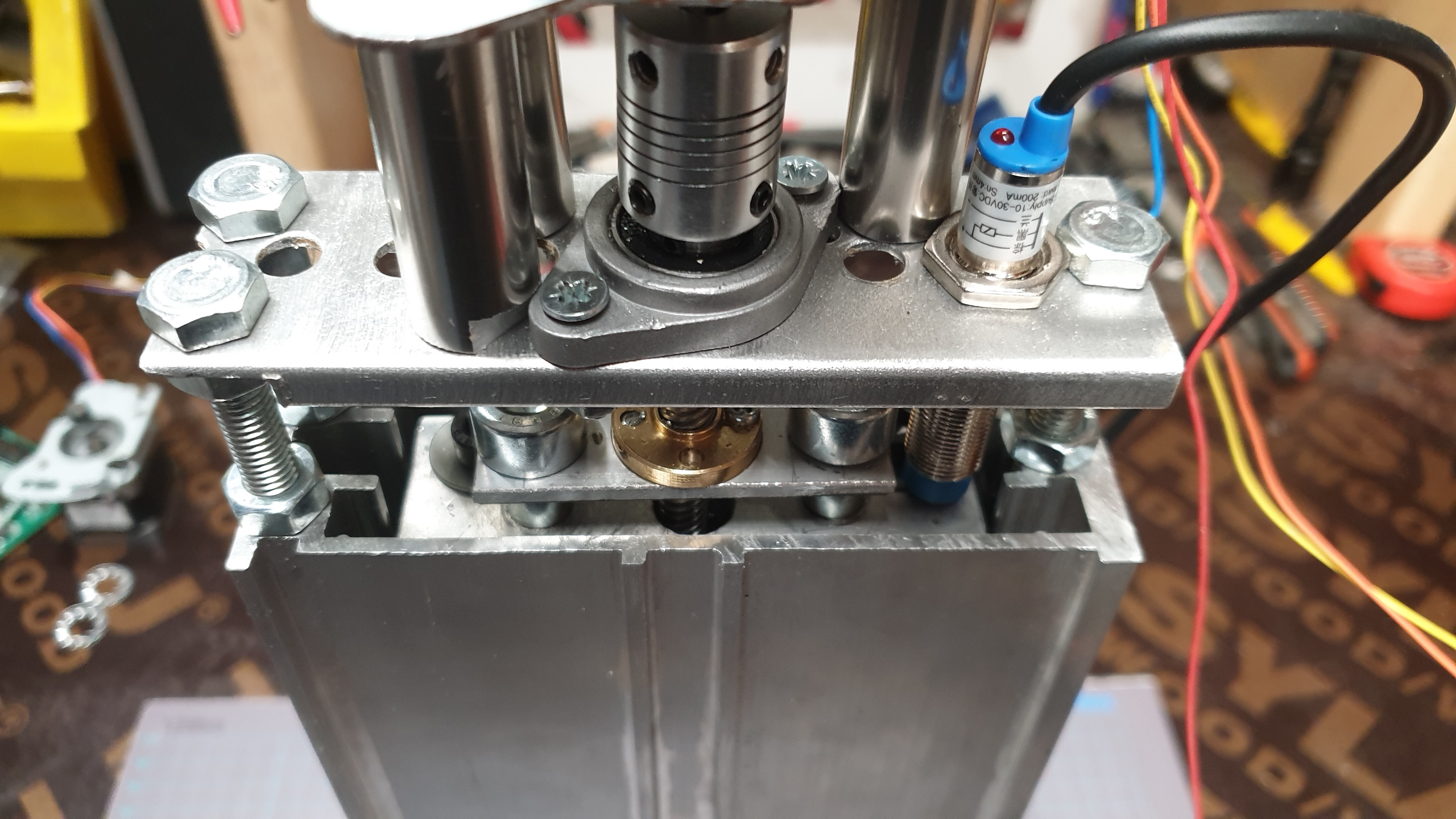
I might get rid of those screws on the top, but that would limit travel by 15mm, so that would leave 150mm of usable travel. Do keep in mind that there is another 10mm travel for the floating part of it, so the only unused space inside is 10mm used by an alu plate connecting the rods inside and holding floating stuff and leadscrew nut, here is a picture of the floating part in the UP position:
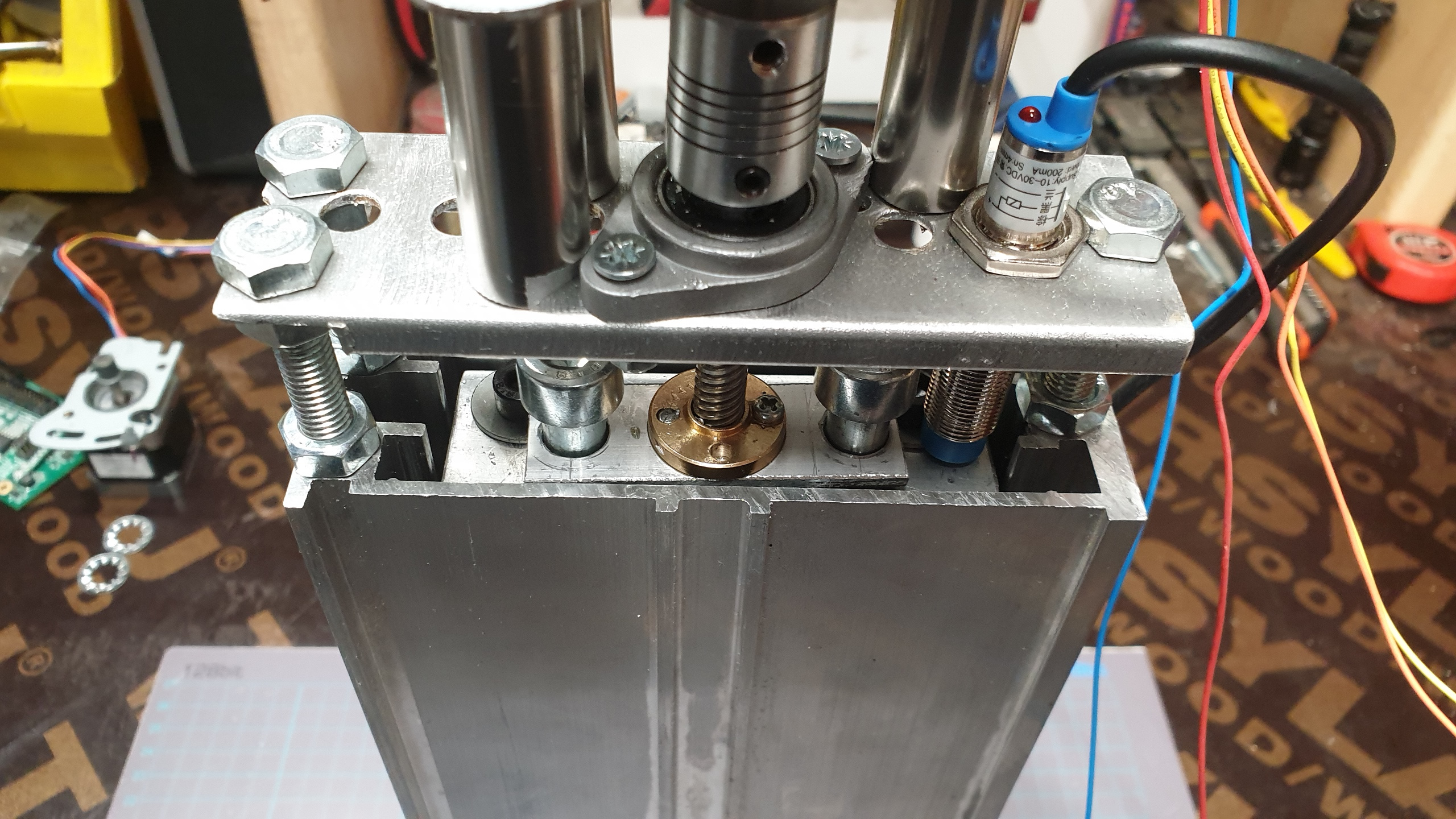
And in the DOWN position, notice there is no sensor/switch there, will have to put that in when i dismantle it to make another one, and maybe take some pictures, :
Here is the back side, plain and clean ( well not cleaned yet, but there is nothing there ) :
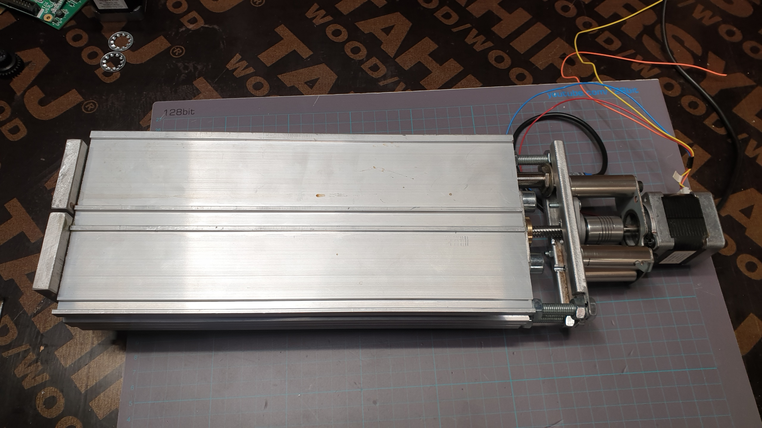
And here it is extended to the bottom limit :
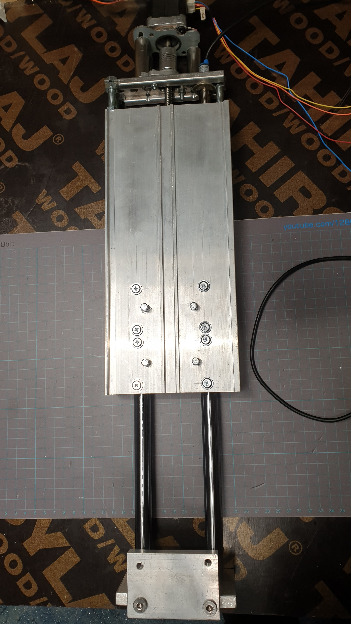
Took two full days to make, several injuries to the left hand ( the one holding down the stuff while the right hand does the damage ), had to use a bit smaller motors (Nema 17), the leadscrew is 8mm pitch and 8mm thick by some miracle of very nice quality, 16mm round rails on the inside with 4 linear bearings, total weight just under 3KG and 128mm wide. The mounting on the machine will have to be done on the sides as there is no place for anything on the back side, any screws there will interfere with the movement.
More on the way.....
This is the final implementation of the Z axis, after many, many others i tried and discarded them for being to heavy/bulky/ugly. :
The profile is 28.5cm long and 34mm wide inside so not much space there for all the stuff that i had to put inside
Travel is 165mm, screw can do 220mm, but the bearing took 100mm inside, so i got left with only 185mm to work with.
I might get rid of those screws on the top, but that would limit travel by 15mm, so that would leave 150mm of usable travel. Do keep in mind that there is another 10mm travel for the floating part of it, so the only unused space inside is 10mm used by an alu plate connecting the rods inside and holding floating stuff and leadscrew nut, here is a picture of the floating part in the UP position:
And in the DOWN position, notice there is no sensor/switch there, will have to put that in when i dismantle it to make another one, and maybe take some pictures, :
Here is the back side, plain and clean ( well not cleaned yet, but there is nothing there ) :
And here it is extended to the bottom limit :
Took two full days to make, several injuries to the left hand ( the one holding down the stuff while the right hand does the damage
), had to use a bit smaller motors (Nema 17), the leadscrew is 8mm pitch and 8mm thick by some miracle of very nice quality, 16mm round rails on the inside with 4 linear bearings, total weight just under 3KG and 128mm wide. The mounting on the machine will have to be done on the sides as there is no place for anything on the back side, any screws there will interfere with the movement.More on the way.....
Attachments:
Please Log in or Create an account to join the conversation.

30 Apr 2020 20:38 #166252
by rodw
Replied by rodw on topic 2+2+3 More Plasma builds, double the joy ! 3X2M and 2.5X1.5M cnc plasma build.
2 days! I took 3 months!
The following user(s) said Thank You: tommylight
Please Log in or Create an account to join the conversation.
- tommylight
-
Topic Author
- Online
- Moderator
-
Less
More
- Posts: 17782
- Thank you received: 5909
30 Apr 2020 20:43 #166253
by tommylight
The main problem, i am running out of aluminium ! Not good, not good.
You took 3 months for the whole machine, i really hope not just for the z Axis ?
Replied by tommylight on topic 2+2+3 More Plasma builds, double the joy ! 3X2M and 2.5X1.5M cnc plasma build.
That is just for the Z axis, but since the day was not over yet i started putting parts together for another 3 and decided on removing the long protruding screws, so it will be just a box with a motor !2 days! I took 3 months!
The main problem, i am running out of aluminium ! Not good, not good.
You took 3 months for the whole machine, i really hope not just for the z Axis ?
Please Log in or Create an account to join the conversation.
30 Apr 2020 21:11 #166258
by rodw
Replied by rodw on topic 2+2+3 More Plasma builds, double the joy ! 3X2M and 2.5X1.5M cnc plasma build.
Nah, 3 months in my spare time just on the Z and Y axis drive including the CAD design (47,000 versions probably) and remaking parts you and Andy made me redesign and a seoncd version of a magnetic breakaway that actually worked. Then I found out parts I might have spent a day or so making were available off the shelf!
The following user(s) said Thank You: tommylight, CNCFred
Please Log in or Create an account to join the conversation.

03 May 2020 05:53 #166470
by CNCFred
Replied by CNCFred on topic 2+2+3 More Plasma builds, double the joy ! 3X2M and 2.5X1.5M cnc plasma build.
What is the material costs without nema17? Approx!
Please Log in or Create an account to join the conversation.
03 May 2020 06:25 #166472
by rodw
Replied by rodw on topic 2+2+3 More Plasma builds, double the joy ! 3X2M and 2.5X1.5M cnc plasma build.
I don't remember but it would not have been that much. A 150 mm 16mm ballscrew, a piece of 15mm linear rail and a couple of carriages I got second hand unused from a guy off ebay and some magnets. I used 60mm x 6mm aluminium flat bar for the Z cos it would fit in my little milling vice on my manual SX3. I think the backing plate for the Y was 160mm x 12mm ally flat bar.
I spent a lot of time milling the part the ballscrew nut is mounted to only to find you can buy them premade! But it was also an exercise in getting more confident with my milling machine. Boring the hole for the torch and slitting it was fun and it worked out nice. Most of the machining was drilling holes and tapping (the SX3 has a tapping mode).
The only things I'd change might be:
1. omit the Z axis min limit switch as it never gets hit with material on the table (or swap the striker plate and switch around)
2. Use a mechanical microswitch for the breakaway as the prox sensor sticks out the back ( it is rare to trigger it)
3. Possibly use a planetry gearbox reduction gear for the X axis drive. The bearings supporting the pinion are not cheap.
4. Review the magnetic breakaway. Its probably better to use 3 larger magnets for easier alignment.
I can sell you the plans BTW complete with provision for a Scribe
Please Log in or Create an account to join the conversation.
03 May 2020 07:10 - 03 May 2020 07:10 #166477
by CNCFred
Replied by CNCFred on topic 2+2+3 More Plasma builds, double the joy ! 3X2M and 2.5X1.5M cnc plasma build.
I haven't got a milling machine.
I bought a Z ready one for 300 Euro, which I think bought in China directly would be much cheaper. In fact I am satisfied.
It's a S series from ccmrails.
Thx for offering your plans. I was very very lucky everything worked out like planed at my build.
I am only thinking replacing rack and pinion for At5 10mm belt which I have already on stock. I am not sure if this would make it worse.
Last edit: 03 May 2020 07:10 by CNCFred.
Please Log in or Create an account to join the conversation.
- Other Stuff
- Show Your Stuff
- 2+2+3 More Plasma builds, double the joy ! 3X2M and 2.5X1.5M cnc plasma build.
Time to create page: 0.234 seconds