how to synchronize two servomotors
15 Jun 2017 14:41 #94539
by Jasper 3
Replied by Jasper 3 on topic how to synchronize two servomotors
Great thanks!
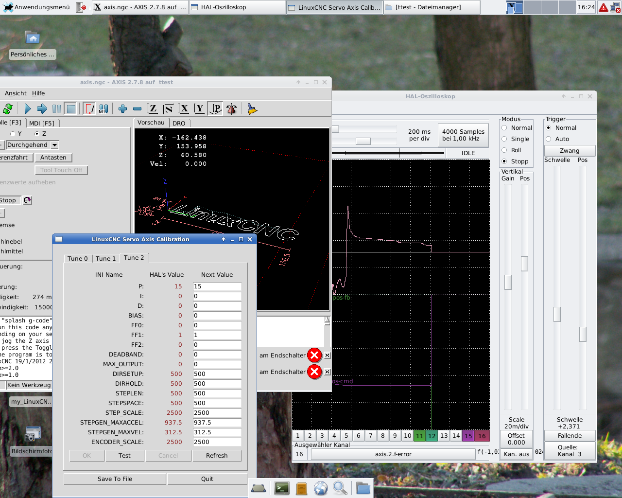
Now everything seems to work well for X.
Now I tune the Z -Axis. The problem is that the f.error graph slowly decreases (oscillating) to zero. Than he overshoots and moves back to zero like in this picture. Any suggestions what I can do?
Now everything seems to work well for X.
Now I tune the Z -Axis. The problem is that the f.error graph slowly decreases (oscillating) to zero. Than he overshoots and moves back to zero like in this picture. Any suggestions what I can do?
Please Log in or Create an account to join the conversation.
- Todd Zuercher
-

- Away
- Platinum Member
-

Less
More
- Posts: 4963
- Thank you received: 1369
15 Jun 2017 15:05 - 15 Jun 2017 15:09 #94542
by Todd Zuercher
Replied by Todd Zuercher on topic how to synchronize two servomotors
Did you change the pid.z.maxerror to zero?
or better yet just comment out this line in your hal file.Don't forget to do this for all of your PID loops.
There are times when having appropriately sized limits on the PID error can be useful, just that this isn't one of them. Nor is that an appropriately sized limit for your system.
or better yet just comment out this line in your hal file.
setp pid.z.maxerror .0005There are times when having appropriately sized limits on the PID error can be useful, just that this isn't one of them. Nor is that an appropriately sized limit for your system.
Last edit: 15 Jun 2017 15:09 by Todd Zuercher.
Please Log in or Create an account to join the conversation.
15 Jun 2017 15:56 #94544
by Jasper 3
Replied by Jasper 3 on topic how to synchronize two servomotors
outch! that hurts! thank you very much!
Please Log in or Create an account to join the conversation.
20 Jun 2017 15:59 #94729
by Jasper 3
Replied by Jasper 3 on topic how to synchronize two servomotors
hey,
i updated to Linuxcnc Master branch. I'm still trying to synchronize my Y-Axis servomotors. In my actual Hal I'm using the Tandemmode but as you already told me this is not the ideal solution.
So I think I need to set an extra Joint in my INI and Hal file for my Y-Axis?
I tryed to set my Inifile like in this link github.com/LinuxCNC/linuxcnc/blob/master.../sim/axis/gantry.ini
But where should I put the PID part? Also I'm not sure how to set up the Halfile.
here are my Hal and Ini files (using the Tandemmode)
here are my configfiles (using the link method)
thanks alot
Please Log in or Create an account to join the conversation.
- Todd Zuercher
-
- Away
- Platinum Member
-
Less
More
- Posts: 4963
- Thank you received: 1369
20 Jun 2017 17:28 #94736
by Todd Zuercher
Replied by Todd Zuercher on topic how to synchronize two servomotors
These are the first obvious problems I see in the INI file. (I haven't looked real close at the hal file yet.)
To start with in your ini fine I think [KINS] section needs changed to
Then In your joint sections, the joints that you have slaved together, need to have the HOME_SEQUENCE set to matching negative numbers. The negative is important, it indicates joints that are to home in a slaved fashion.
The joints are homed in the order specified by the absolute values of the HOME_SEQUENCE numbers. On a mill or router it is generally best to home the Z axis first, to get it up and out of the way. So for your config I'd suggest using home sequence values of Z=0 X=1 and Y and Y2 = -1 or -2 (I usually home my X and Y at the same time). If X=1 and the Ys=-1 X and both Ys will home at the same time but the Ys will home slaved together. and wait for each other at the limit switch and any changes of direction. (If the Ys and X can't home at the same time for any reason, such as shared switch inputs, then use -2 for the Ys.)
Finally, I am not certain if this will cause a problem, but I highly recommend putting all of the joint/axis sections in the numerical order of the joints. I think how it is now with Y2-Joint3 before Z-Joint2 could cause problems.
To start with in your ini fine I think [KINS] section needs changed to
[KINS]
JOINTS = 4
KINEMATICS = trivkins coordinates=XYZY
Then In your joint sections, the joints that you have slaved together, need to have the HOME_SEQUENCE set to matching negative numbers. The negative is important, it indicates joints that are to home in a slaved fashion.
The joints are homed in the order specified by the absolute values of the HOME_SEQUENCE numbers. On a mill or router it is generally best to home the Z axis first, to get it up and out of the way. So for your config I'd suggest using home sequence values of Z=0 X=1 and Y and Y2 = -1 or -2 (I usually home my X and Y at the same time). If X=1 and the Ys=-1 X and both Ys will home at the same time but the Ys will home slaved together. and wait for each other at the limit switch and any changes of direction. (If the Ys and X can't home at the same time for any reason, such as shared switch inputs, then use -2 for the Ys.)
Finally, I am not certain if this will cause a problem, but I highly recommend putting all of the joint/axis sections in the numerical order of the joints. I think how it is now with Y2-Joint3 before Z-Joint2 could cause problems.
Please Log in or Create an account to join the conversation.
22 Jun 2017 09:11 #94782
by Jasper 3
Replied by Jasper 3 on topic how to synchronize two servomotors
hey,
now I can open Linuxcnc. But I had to # something out.
(
#net y-output => hm2_5i25.0.stepgen.06.velocity-cmd
#net y-enable => hm2_5i25.0.stepgen.06.enable
and the same for
#net y2-output => hm2_5i25.0.stepgen.06.velocity-cmd
#net y2-enable => hm2_5i25.0.stepgen.06.enable
)
I'm not sure where I should connect the Joints. Is there any example hal file?
When I run the homing it tells my that my kinematic settings are worng.
greets Jasper
Please Log in or Create an account to join the conversation.
- Todd Zuercher
-
- Away
- Platinum Member
-
Less
More
- Posts: 4963
- Thank you received: 1369
22 Jun 2017 12:27 #94784
by Todd Zuercher
Replied by Todd Zuercher on topic how to synchronize two servomotors
You have most of the mesa card connections for Y and Y2 set to the same stepgenerator in your hal file. This is very wrong. Linuxcnc failed to start because some of those duplication were trying to connect the same hal pins to different signal names.
You need to figure out which stepgens (and which physical pins on the Mesa card) you have the step driver connected to. If you have Y2 connected to the output that is controlled by stepgen.07 (is that right?) then you need to change everything in the Y2 section from hm2_5i25.0.stepgen.06 to hm2_5i25.0.stepgen.07.
Something like this.
#*******************
#  JOINT Y2
#*******************

setp   pid.y2.Pgain     [JOINT_3]P
setp   pid.y2.Igain     [JOINT_3]I
setp   pid.y2.Dgain     [JOINT_3]D
setp   pid.y2.bias      [JOINT_3]BIAS
setp   pid.y2.FF0       [JOINT_3]FF0
setp   pid.y2.FF1       [JOINT_3]FF1
setp   pid.y2.FF2       [JOINT_3]FF2
setp   pid.y2.deadband  [JOINT_3]DEADBAND
setp   pid.y2.maxoutput [JOINT_3]MAX_OUTPUT
setp   pid.y2.error-previous-target true
#setp   pid.y2.maxerror .0005

net y2-index-enable  <=> pid.y2.index-enable
net y2-enable        =>  pid.y2.enable
net y2-pos-cmd       =>  pid.y2.command
net y2-vel-cmd       =>  pid.y2.command-deriv
net y2-pos-fb        =>  pid.y2.feedback
net y2-output        =>  pid.y2.output

# Step Gen signals/setup

setp   hm2_5i25.0.stepgen.07.dirsetup        [JOINT_3]DIRSETUP
setp   hm2_5i25.0.stepgen.07.dirhold         [JOINT_3]DIRHOLD
setp   hm2_5i25.0.stepgen.07.steplen         [JOINT_3]STEPLEN
setp   hm2_5i25.0.stepgen.07.stepspace       [JOINT_3]STEPSPACE
setp   hm2_5i25.0.stepgen.07.position-scale  [JOINT_3]STEP_SCALE
setp   hm2_5i25.0.stepgen.07.step_type        0
setp   hm2_5i25.0.stepgen.07.control-type     1
setp   hm2_5i25.0.stepgen.07.maxaccel         [JOINT_3]STEPGEN_MAXACCEL
setp   hm2_5i25.0.stepgen.07.maxvel           [JOINT_3]STEPGEN_MAXVEL

# ---closedloop stepper signals---

net y2-pos-cmd    <= joint.3.motor-pos-cmd
net y2-vel-cmd    <= joint.3.vel-cmd
net y2-output     <= hm2_5i25.0.stepgen.07.velocity-cmd
#net y2-pos-fb     <= hm2_5i25.0.stepgen.07.position-fb
net y2-pos-fb     => joint.3.motor-pos-fb
net y2-enable     <= joint.3.amp-enable-out
net y2-enable     => hm2_5i25.0.stepgen.06.enable

# ---closedloop stepper signals---

net y2-output                             => hm2_5i25.0.stepgen.07.velocity-cmd
net y2-enable                             => hm2_5i25.0.stepgen.07.enable

# ---Encoder feedback signals/setup---

setp    hm2_5i25.0.encoder.04.counter-mode 0
setp    hm2_5i25.0.encoder.04.filter 1
setp    hm2_5i25.0.encoder.04.index-invert 0
setp    hm2_5i25.0.encoder.04.index-mask 0
setp    hm2_5i25.0.encoder.04.index-mask-invert 0
setp    hm2_5i25.0.encoder.04.scale  [JOINT_1]ENCODER_SCALE

net y2-pos-fb               <=  hm2_5i25.0.encoder.04.position
net y2-vel-fb               <=  hm2_5i25.0.encoder.04.velocity
net y2-pos-fb               =>  joint.3.motor-pos-fb
net y2-index-enable    joint.3.index-enable  <=>  hm2_5i25.0.encoder.04.index-enable
net y2-pos-rawcounts        <=  hm2_5i25.0.encoder.04.rawcounts

# ---setup home / limit switch signals---
#net y2-neg-limit  <= hm2_5i25.0.7i76.0.0.input-05-not
#net y2-pos-limit  <= hm2_5i25.0.7i76.0.0.input-04-not
net y2-home-sw    <= hm2_5i25.0.7i76.0.0.input-17
net y2-home-sw     =>  joint.3.home-sw-in
#net y2-neg-limit     =>  joint.3.neg-lim-sw-in
#net y2-pos-limit     =>  joint.3.pos-lim-sw-in
Please Log in or Create an account to join the conversation.
22 Jun 2017 14:17 #94785
by Jasper 3
Replied by Jasper 3 on topic how to synchronize two servomotors
thanks that was defentiv one mistake (y is stepgen6 and y2 is stepgen 7). So know I still get following errors.
I discovered. that one motor rotates backwards. Also this motor has under calibration (in axis) no encoder feedback. If I change the sign. (y stays - ; y2 becomes +) than both motors turn in the same direction. But there still must be an error. Imidetly after moving the y-axis I get either following error 1 or 3.
I discovered. that one motor rotates backwards. Also this motor has under calibration (in axis) no encoder feedback. If I change the sign. (y stays - ; y2 becomes +) than both motors turn in the same direction. But there still must be an error. Imidetly after moving the y-axis I get either following error 1 or 3.
Please Log in or Create an account to join the conversation.
- Todd Zuercher
-
- Away
- Platinum Member
-
Less
More
- Posts: 4963
- Thank you received: 1369
22 Jun 2017 16:12 #94794
by Todd Zuercher
Replied by Todd Zuercher on topic how to synchronize two servomotors
The first thing you are going to need to do is get the encoder feedback straightened out for each joint.
It might be useful while setting things up if you can see the DROs in Joint mode. To enable that, in your ini file under the [KINS] section change the Kinimatics line to
KINEMATICS = trivkins coordinates=XYZY kinstype=BOTH
Then the joint values will be shown in the DRO.
DO NOT try to jog the y axis joints while in joint mode. As they will not be slaved together in joint mode and doing so will rack your gantry.
Just remember to take that out after the machine is setup so you can't rack the gantry.
With the drives disabled, push the gantry and see if the DROs for both Y joints moves correctly.
Then make the nessisary adjustments to the scales for those joints. (assuming the encoders are wired up and working correctly.) Also be sure that you have the right encoder connected to Y1 and Y2. (that they are not crossed)
Please Log in or Create an account to join the conversation.
22 Jun 2017 18:01 #94796
by Jasper 3
Replied by Jasper 3 on topic how to synchronize two servomotors
really awesome!
thanks found out that the encoder cables were switched. So no it is working. Just need to tune the axis because the axis oscillates. Or can there be another reason for that oscillations.
Greets
thanks found out that the encoder cables were switched. So no it is working. Just need to tune the axis because the axis oscillates. Or can there be another reason for that oscillations.
Greets
Please Log in or Create an account to join the conversation.
Time to create page: 0.224 seconds