ATC motor braking circuit
04 Sep 2023 08:40 - 04 Sep 2023 08:41 #279801
by camb0
ATC motor braking circuit was created by camb0
Hi,
I'm retrofitting a Matsuura MC500v Mill and I'm about to tackle the tool changer.
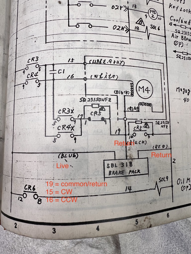
It's got 100v AC reversible motor powering the tool carousel with a reduction gear box, the original design uses a brake module (3 wire) and a set of relays, capacitors and a brake module to ‘brake’ the motor once the power is disconnected from driving the motor.
I’ve attached the wiring diagram from the MC500 manual (its the hand drawn one), the motor is M4, I don’t know what’s in the brake pack and I can’t peek inside it w/o breaking it and there’s isn’t a manual I can find for the brake pack, oh C1 doesn't have a label but is size wise in between a battery size C and D.
As I don't quite understand what the brake pack is doing I’m wondering if there’s a simpler way to re-wire it, a couple of options I could think of were:
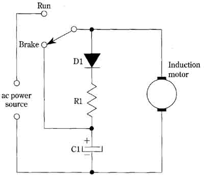
1) Use a capacitor and resistor to brake it after power off as per the attached diagram (but with circuits for fwd and rev), ie the capacitor drains it power through the motor in reverse OR
2) Could I use a two relays (solid state for convenience) and when I want to stop the carousel I get linuxcnc just pulse the motor in the opposite direction for a really short period of time (0.1s? )
 d
d
Thanks in advance,
Cam.
I'm retrofitting a Matsuura MC500v Mill and I'm about to tackle the tool changer.
It's got 100v AC reversible motor powering the tool carousel with a reduction gear box, the original design uses a brake module (3 wire) and a set of relays, capacitors and a brake module to ‘brake’ the motor once the power is disconnected from driving the motor.
I’ve attached the wiring diagram from the MC500 manual (its the hand drawn one), the motor is M4, I don’t know what’s in the brake pack and I can’t peek inside it w/o breaking it and there’s isn’t a manual I can find for the brake pack, oh C1 doesn't have a label but is size wise in between a battery size C and D.
As I don't quite understand what the brake pack is doing I’m wondering if there’s a simpler way to re-wire it, a couple of options I could think of were:
1) Use a capacitor and resistor to brake it after power off as per the attached diagram (but with circuits for fwd and rev), ie the capacitor drains it power through the motor in reverse OR
2) Could I use a two relays (solid state for convenience) and when I want to stop the carousel I get linuxcnc just pulse the motor in the opposite direction for a really short period of time (0.1s? )
Thanks in advance,
Cam.
Attachments:
Last edit: 04 Sep 2023 08:41 by camb0.
Please Log in or Create an account to join the conversation.

04 Sep 2023 09:14 #279805
by andypugh
Replied by andypugh on topic ATC motor braking circuit
It is probably using DC injection braking:
en.wikipedia.org/wiki/DC_injection_braking
You might be able to re-use the existing module?
Also, some VFDs can provide DC injection.
Another option might be to swap the motor to a servo or stepper.
en.wikipedia.org/wiki/DC_injection_braking
You might be able to re-use the existing module?
Also, some VFDs can provide DC injection.
Another option might be to swap the motor to a servo or stepper.
Please Log in or Create an account to join the conversation.
04 Sep 2023 23:48 #279899
by camb0
Replied by camb0 on topic ATC motor braking circuit
Andy thx for the reply, yes It's a DC injection circuit of sorts but my simple brain can't quite work out the control signal and sequencing of the relay switching, I probably need to trace it out on a signal diagram and redraw the circuit so I understand it better.
I might just start what the simplest approach (using the least components) 2-3 relays driven from the MESA board and see how I go, If I were to spend $$ and upgrade anything I really like your suggestion of converting to a stepper motor.
Also I'm concerned the brake module is 40 years old and I probably can't find a replacement with the same wiring, well not from internet searches (time investment of figuring out the circuit V $$ investment of a stepper ... hmm)
Please Log in or Create an account to join the conversation.
04 Oct 2023 05:27 #282249
by camb0
Replied by camb0 on topic ATC motor braking circuit
Just closing this out.
The reverse motor worked to brake it.
I ended up driving the carousel from classicladder (CL).
I setup four motor signals for the carousel, two for CW and two for CWW, one is the direct connection and the other goes through a 'timedelay' hal pin. I exposed the 4 of those in CL and connected two CL inputs to the carousel component.
So if I'm turning it CW I use the 'falling' signal sensor/switch in CL to catch it and then call the CCW with the delay pin. I tried with a CL timer and it was to slow. I ended settling on a 0.020 of second delay utilizing a solid state relay from the MESA 7i76 board.
Please Log in or Create an account to join the conversation.
Time to create page: 0.227 seconds