- Configuring LinuxCNC
- Advanced Configuration
- Dual PID loops with motor encoder + scale encoder per axis
Dual PID loops with motor encoder + scale encoder per axis
- TangentAudio
- Offline
- Junior Member
-

- Posts: 35
- Thank you received: 3
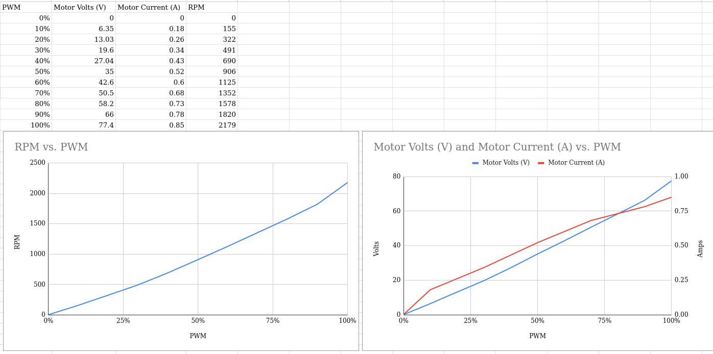
Except for the discontinuity at the bottom, voltage looks more linear to me, though they both look reasonably linear.


Attachments:
Please Log in or Create an account to join the conversation.
- TangentAudio
- Offline
- Junior Member
-
- Posts: 35
- Thank you received: 3
Another observation: when I run the motor at a fixed PWM value and apply a physical load to the motor, current will jump up substantially but the voltage will drop a much smaller amount percentage-wise. So it behaves more like a CV power supply and not a CC power supply. The voltage drop could be explained by the 10ft long 16 gauge wire that feeds the motor.
Attachments:
Please Log in or Create an account to join the conversation.
- TangentAudio
- Offline
- Junior Member
-
- Posts: 35
- Thank you received: 3
An apparent quote from PCW, found at the very bottom of wiki.linuxcnc.org/cgi-bin/wiki.pl?Servo_Tuning_Detail_How_To
Bare H-bridge drives running PM DC motors behave somewhat like velocity mode servos
(with quite low velocity feedback gain) So they end up being somewhere between velocity
and torque mode.
That is, you are setting the average motor drive voltage with the PWM value. This sets the
approximate motor velocity because the motor will accelerate to a velocity where the generated
back EMF is close to the supplied voltage. If the motor impedance was zero, you would have close
to a perfect velocity mode servo, but the impedance is substantial which leads to the low
inherent feedback gain.
Normally for Hbridges, I would start with a low P value and tune the D term as high as
possible without excessive buzzyness, then set FF1 so that the actual position does
not lead or lag the commanded position at full speed, then I would tune FF2 so that
the actual position does not lead or lag the commanded position during acceleration
Then I would tune P as high as possible without oscillation, overshoot and then when
everything else is close, add as much I term as possible without instability.
Please Log in or Create an account to join the conversation.
In Torque-mode, the command dictates the amount of current applied to the motor. Remove the command and the motor will coast to a stop and then the shaft can be easily rotated by hand, as if the drive was dis-abled.
Please Log in or Create an account to join the conversation.
- TangentAudio
- Offline
- Junior Member
-
- Posts: 35
- Thank you received: 3
This is why that quote from PCW caught my eye - he says PWM H-bridge drives appear to work as a hybrid between velocity and torque mode drives. H-bridge seems likely to me as they are simple and relatively low-cost, and this would not have been an exceptionally high-end system back in the 1980s.
So maybe this is all good news? I should be able to make an inner velocity PID loop that takes in commanded velocity from an outer position loop, and uses the motor encoder velocity for feedback.
Please Log in or Create an account to join the conversation.
Provided that the control system is capable of handling position and velocity control, a dumb drive keeps things simple.
Craig
Please Log in or Create an account to join the conversation.

(the inherent velocity feedback from the BEMF makes it so)
At 0 voltage, the shaft _will_ resist turning because it acts as a generator
into a shorted load. In fact, if the PWM and motor had 0 resistance it would
hold position!
This similarity to velocity mode also is illustrated in the tuning which
matches velocity mode tuning in that the FF1 term (that compensates for BEMF)
is critical. (torque mode tuning typically uses no FF1)
Please Log in or Create an account to join the conversation.
- TangentAudio
- Offline
- Junior Member
-
- Posts: 35
- Thank you received: 3

Please Log in or Create an account to join the conversation.
- TangentAudio
- Offline
- Junior Member
-
- Posts: 35
- Thank you received: 3
If we assume it is a velocity-like drive, I'm a bit confused about the topology of the PID loops, especially the inner one in this dual loop scenario.
Rather than the summed dual loop that I diagrammed several days ago in this thread (the one that splits PD and I across the two loops), it seems like it's preferable to have the two loops cascade? In other words, outer loop takes a position command from the axis joint and uses the linear scale encoder position value to close that loop. The output from the outer loop would be a velocity command fed into the inner loop, which would use the velocity from the motor encoder as its feedback.
Here's my main point of confusion, however: wouldn't the output of that inner loop would be a torque command and not a velocity command? How do we use that when the PWM drives seem to expect a velocity input. Am I wrong in my understanding that the output of the loop is the derivative of its command/feedback ?
Please Log in or Create an account to join the conversation.
With no motor command, they freely rotate.
When the loop is closed, I absolutely need the D-term (of the PID) or I have unacceptable overshoot.
These are the characteristics of an industrial drive in torque-mode (aka: current mode).
Craig
Please Log in or Create an account to join the conversation.
- Configuring LinuxCNC
- Advanced Configuration
- Dual PID loops with motor encoder + scale encoder per axis