×
Forum Header
Sound Logic Combo Board Pinout Question
23 Oct 2014 07:43 #52314
by sgsracing
Sound Logic Combo Board Pinout Question was created by sgsracing
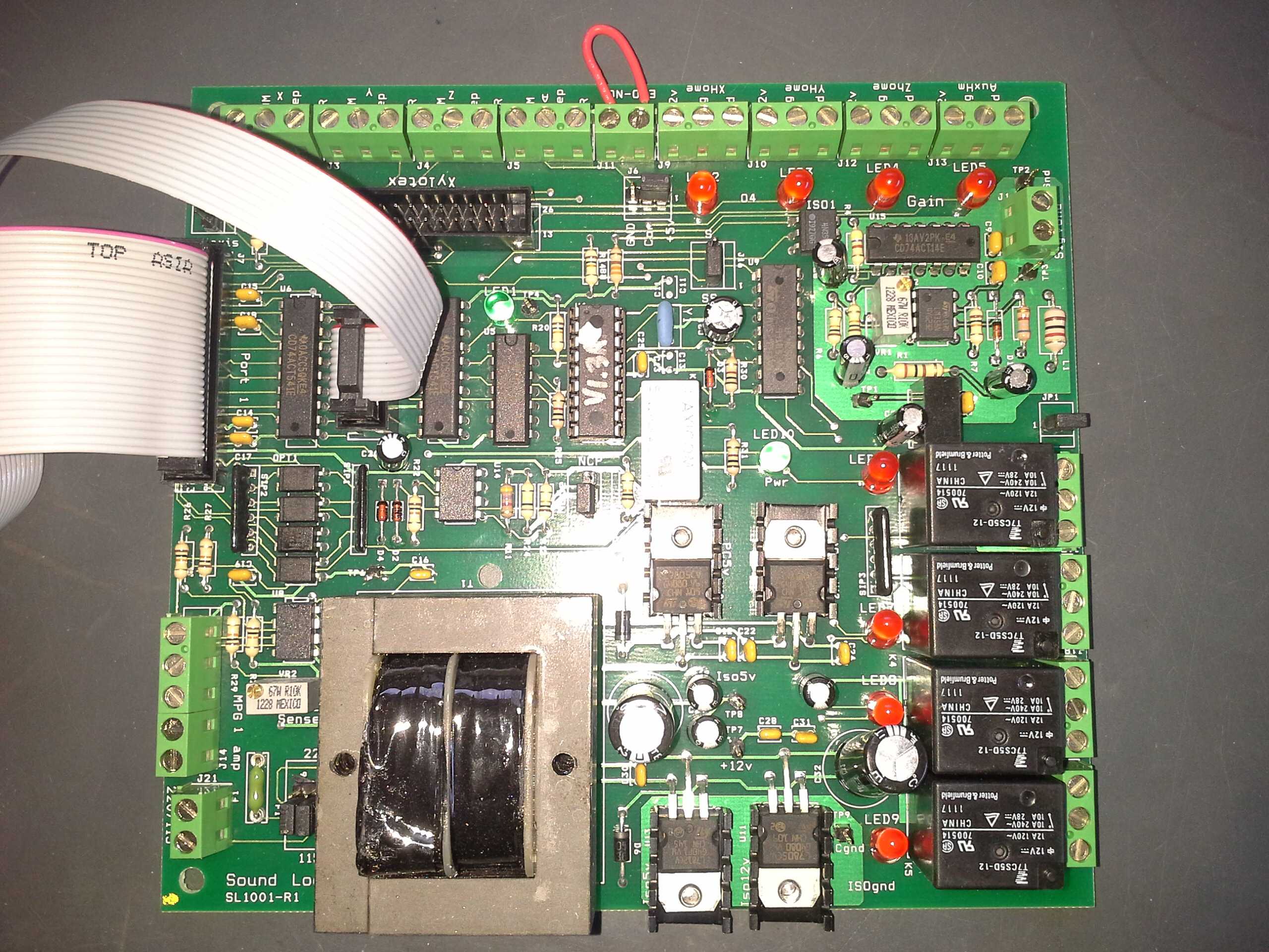
I have a Sound Logic combo board. I am using Linux CNC on 10.04 I have a question about the pinout required for this combo board. The manual for this board is a bit confusing and I'm not sure which pins are used to turn the spindle on and which pins are used to create an analog signal to the VFD. Any help would be greatly appreciated. I am interfacing with an hitachi NE-S1 VFD. Which uses a a 0-10vdc input coming from the combo board. Which parallel port pins do this? Or does a digital signal get converted to 0-10vdc on the board? How do I assign my pinout to ensure this works? Attched is a picture of my board.
Thank you!
Thank you!
Please Log in or Create an account to join the conversation.
23 Oct 2014 15:32 - 23 Oct 2014 15:33 #52324
by cncbasher
Replied by cncbasher on topic Sound Logic Combo Board Pinout Question
the spindle is controlled by pin 14 for forward/reverse , and pin 1 as spindle pwm
J16 is your spindle on or run relay
J17 as your spindle direction
j2 is your analog out to your vfd use ground and sig as input
the board has a convertor so you should not need to do anything
see notes over wiring the run and direction relays
basicly wire the run relay in the common feed of the direction relay
i dont have a manual on the ne-s1 at the moment , but shout and we can advise if you have the manual to hand or pdf
the charge pump may be the awkward point , but their are configs that show the configuration needed
once you have your basic configuration , add the charge pump last , as once you need to edit the configuration by hand
you loose the ability to use stepconf , so easy to make 2 and keep one for editing and then copy snipets of code across
Last edit: 23 Oct 2014 15:33 by cncbasher.
The following user(s) said Thank You: sgsracing
Please Log in or Create an account to join the conversation.
23 Oct 2014 22:32 #52333
by sgsracing
Replied by sgsracing on topic Sound Logic Combo Board Pinout Question
Excellent!! Ok so to clarify...
- I need to set Linuxcnc Pinout pin1 to "Spindle PWM". This pin is then converted in my breakout board to the Analog 0-10VDC.
- Linuxcnc Pin 14 is set to "Spindle CW" ( This is the Direction Relay on my Combo Board.)
- Does the "Spindle Run" relay turn on when there is PWM on pin1? There is no input pin for "Spindle run" on my board input so I am guessing that the board does this for me?
- Interlocking Direction and Run relay makes perfect sense.
- Charge pump.... OK so my understanding is the board will not work unless the charge pump pin is activated. The relay then is optional and can be used to run something that I need all the time to run such as dust collection?
Thank you very much for the help!
I have added both my VFD Manual and my Combo board manual for all to see.
Please Log in or Create an account to join the conversation.
23 Oct 2014 22:49 #52334
by cncbasher
Replied by cncbasher on topic Sound Logic Combo Board Pinout Question
my answer is yes ! ... if the pwm os zero then the run relay is off , or at least thats how i read it
see how you go we can sort out any problems as you go ..
see how you go we can sort out any problems as you go ..
The following user(s) said Thank You: sgsracing
Please Log in or Create an account to join the conversation.
23 Oct 2014 22:57 #52335
by sgsracing
Replied by sgsracing on topic Sound Logic Combo Board Pinout Question
Great! I will proceed and update as I learn more!
Thanks again!
Thanks again!
Please Log in or Create an account to join the conversation.
Time to create page: 0.352 seconds