G38.2 randomly stops
- JoeHildreth
- Offline
- Premium Member
-

- Posts: 84
- Thank you received: 14
You have given me a lot of great information. Now, I realize there may be a LOT of flaws with my wiring setup, I will attach a couple of pictures of my electronics drawer and perhaps you can give me some pointers in cleaning it up.
I built a small computer rack in the stand of my machine to house the electronics, computer etc. The drawer that I made was broke from some sheet metal and rails added to it. In the pictures you will see (2) 36V supplies for the stepper controllers, a 5V supply on its edge to supply the BOB. (4) stepper controllers and the BOB. The BOB is held off the bottom of the drawer with plastic standoffs. Everything else is directly attached. Motor wires run to 4 pin MIC jacks (The top row) The bottom row is 2 pin MIC The ground wire runs to the supplies, but not to the drawer itself. You see I have signal wires and motor wires bundled together. Here are a few things that I think need to happen.
1) The motor wires are bundles alongside the signal wires of the BOB. These probably should be routed in two groups?
2) In network wiring, it is common practice to twist the pairs to help prevent cross talk. Should I do that for the signal wires as well? Should I do it for the motor wires?
3) I probably should attach the The AC and Power supply grounds to the metal drawer itself. That would create a grounded plane to work with. I may have to scrape some paint off in some areas.
Now some questions.
1) The screen ... Not sure if I am following you. Are you saying the screen goes over the electronics in the drawer and the screen gets grounded?
2) Do you or others have recommendations to make my wire job better?
Joe


Please Log in or Create an account to join the conversation.

2) Do you or others have recommendations to make my wire job better?
It's nice and neat, at least.
I like to use ferrules into cage-clamps when using stranded wire:
www.rapidonline.com/cables-connectors/rv...-pack-of-100-33-1280
Please Log in or Create an account to join the conversation.
1) The screen ... Not sure if I am following you. Are you saying the screen goes over the electronics in the drawer and the screen gets grounded?
There are cables with either braided tinned copper wire or foil as the outer covering bar one.

If this outer screening is grounded it will protect the signal in the inner core(s)
If your components are grounded within a metal enclosure, that will also assist with screening.
Often all the components are mounted on an aluminium back plane or plate for that reason.
Just need to make sure that any clean independent power sources used, on the input side of the optos on the BOB for example, is not grounded to the
main power supply ground.
regards
Please Log in or Create an account to join the conversation.
- JoeHildreth
- Offline
- Premium Member
-
- Posts: 84
- Thank you received: 14
2) Do you or others have recommendations to make my wire job better?
It's nice and neat, at least.
I like to use ferrules into cage-clamps when using stranded wire:
www.rapidonline.com/cables-connectors/rv...-pack-of-100-33-1280
Great suggestion. Andy. I will order some of these and the crimper for my rewire.
One other thing, I think The thread should be moved maybe to a wiring forum. I didn't notice one when looking through the list of forum topics. Maybe it would be a good idea to create one. Thanks for the tip.
Joe
Please Log in or Create an account to join the conversation.
- JoeHildreth
- Offline
- Premium Member
-
- Posts: 84
- Thank you received: 14
OK, That cleared it up for me. Thanks!
If your components are grounded within a metal enclosure, that will also assist with screening.
Often all the components are mounted on an aluminium back plane or plate for that reason.
Just need to make sure that any clean independent power sources used, on the input side of the optos on the BOB for example, is not grounded to the
main power supply ground.
My controllers and PSU's are fastened to the metal enclosure I made for my electronics drawer. I will take the ground from the AC line and bring it to the case and will do this for the 36VDC PSU's. Also, would it be wise to run an additional ground wire from the Ground on my controllers to the case, or will the supply be enough.
My 5VDC supply currently supplies the BOB. I was going to use this supply to run two small 5vdc cooling fans and supply input logic voltages. Are you saying this supply should should not share a ground with the other equipment? (Because I plan to use it to supply signal voltage to the BOB input pins?
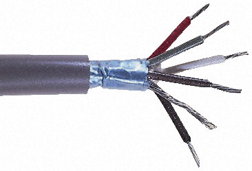
I have some shielded wire like you have shown me. It has 4 22AWG wires and a metal braid. I will use this wire from my drivers to the 4 pin MIC connectors on the back. I should ground the metal braid to the case in my controller box, correct? Not the 2 pairs that are in this wire are not twisted pairs, does that matter, or should I be looking for a different kind of wire? I plan on these connections to run from the controller to the MIC plugs away from the signal lines. On the output side of the MIC jacks, the motors are connected using (2) 22AWG Twisted pairs. Should I replace this with the shielded cable as well? My controllers are running at 3A, according to the AWG chart I should be good with 22AWG wire, but would there be any benefit to bumping it up to 20AWG or 18AWG?
My signal lines ... I thing I will change the wire I am using with some CAT 5 twisted pairs. Would putting a small ferrite bead on each end of the wire be beneficial?
I will take Andy's advice and terminate the wire ends with ferrules on the braided wire.
In reference to the SSR. I looked around a bit looking for something that was 24-36VDC input and would drive TTL Voltages on the output. I am not really finding anything like that. I do however, have a couple dozen or so 24VDC mechanical relays I salvaged from an old Nurse call system. Could I use these for my probe and limit switches and the contacts for the TTL voltages? Would they inject noise or anything that I need to avoid. I have some space in my drawer that I can keep them a couple inches or so away from the BOB.
I appreciate the patience you and Andy have extended to me. As I get my ducks in order, I will pass this information along to the community. (Although, I think a wiring forum added here would be a great addition.)
Regards,
Joe Hildreth
Please Log in or Create an account to join the conversation.
My 5VDC supply currently supplies the BOB. I was going to use this supply to run two small 5vdc cooling fans and supply input logic voltages. Are you saying this supply should should not share a ground with the other equipment? (Because I plan to use it to supply signal voltage to the BOB input pins?
Some BOBs have the provision for each side of the opto isolators to be powered seperately, normally the input side is the side that takes the isolated power supply.
I was just pointing out that sharing a ground with an isolated supply kind of defeats the object.
My controllers and PSU's are fastened to the metal enclosure I made for my electronics drawer. I will take the ground from the AC line and bring it to the case and will do this for the 36VDC PSU's. Also, would it be wise to run an additional ground wire from the Ground on my controllers to the case, or will the supply be enough.
I think the cases are usually grounded anyway for safety reasons, soon find out with a continuity tester.
There are different schools of thought.
I tend to ground everything on the AC side seperately from the DC side and have the transformer as an isolating component, since there is no physical contact between the two sides, just induction.
I think this is why you will sometimes see aluminium back planes inside machines on insulated stand-offs. All the DC components are grounded to it and the machine itself is grounded to AC earth for safety.
But I am not any sort of wiring guru

n reference to the SSR. I looked around a bit looking for something that was 24-36VDC input and would drive TTL Voltages on the output. I am not really finding anything like that. I do however, have a couple dozen or so 24VDC mechanical relays I salvaged from an old Nurse call system. Could I use these for my probe and limit switches and the contacts for the TTL voltages? Would they inject noise or anything that I need to avoid. I have some space in my drawer that I can keep them a couple inches or so away from the BOB.
Before I used a SSR, I used little 12v PCB relays quite happily. The only noise you might get is on contacts making or breaking and that should be when you are getting or losing a signal anyway.
I certainly had no trouble on the limits, which were on a permanently activated line through the switches to the relay coil and broke the contacts if one of the switches did.
regards
Please Log in or Create an account to join the conversation.
- JoeHildreth
- Offline
- Premium Member
-
- Posts: 84
- Thank you received: 14
Some BOBs have the provision for each side of the opto isolators to be powered separately, normally the input side is the side that takes the isolated power supply.
I was just pointing out that sharing a ground with an isolated supply kind of defeats the object.
My BOB is driven with buffers rather than opto-isolators. The 5V PSU supplies the power to the buffers and the rest of the card. So this sound like I should keep a separate ground for this PSU.
I tend to ground everything on the AC side separately from the DC side and have the transformer as an isolating component, since there is no physical contact between the two sides, just induction.
Isn't the AC ground usually connected to the case of a PSU? In this instance the AC ground is already tied to the metal of my drawer. I will take a meter and double check. So it sounds like I would benefit from a raised ground plane.
So if I understand all the conversation we have had, the following will be my plan of attack when rewiring my electronics enclosure. Please indicate if I have missed something.
1) Attach a raised isolated plane from the drawer to physically mount the drivers to.
2) Attach the ground of both 36V PSU to this ground plane
3) Use four strand shielded cable from the motor outputs to the 4 pin MIC connectors at the back of the drawer.
4) Ground the shielding of the motor cables to this ground plane.
5) Use twisted pairs with ferrous beads on each end to supply power to the drivers.
6) Install a ground bus bar or sorts for the 5v PSU and use this ground point for all my TTL signal grounds.
7) Use twisted pairs for all 5V power feeds with ferrous beads on each end.
8) Used twisted pairs for all signal wires.
9) Tie all AC grounds together.
Thank you ArcEye, you have helped me more than you know. I will do a write up of all as I do the wiring. When I am finished, perhaps you and others can give it a go over for correctness, and then post it for the rest of the community to use.
Regards,
Joe
Please Log in or Create an account to join the conversation.
1) Attach a raised isolated plane from the drawer to physically mount the drivers to.
2) Attach the ground of both 36V PSU to this ground plane
As you say the case is probably grounded to AC earth anyway.
I have seen it done and done it both ways, I tend to isolate AC from DC, but that does not mean it is the correct or the only right thing to do.
It will be quite difficult to achieve in a control box, because the metal of the sockets etc is usually the ground and in contact with the chassis anyway,
unless they go through a non conductive plate.
I would not go to any extra expense or trouble to follow my quirks!
Unless you get any problems, a common ground for all non-isolated supplies is probably fine and much easier to achieve.
regards
Please Log in or Create an account to join the conversation.
- JoeHildreth
- Offline
- Premium Member
-
- Posts: 84
- Thank you received: 14
Thanks for all your help. I think I am going to follow the plan I have and see how it affects things. Look anything has to be better than what I originally done. Motor wire, control wires, PSU wires all bundled together had to be asking for trouble. This can only make it better. Aside from the cost of the crimper for the ferrules, it isn't costing me much to do. This is a hobby machine for hobby use so as long as the wiring is sound and trying to follow some best practice, I feel like I will be OK. I owe you and Andy a great thanks for all the help. If either of you are ever in middle Tennessee, I will be happy to buy you dinner and a few cold ones.
I am hoping that with the rewiring of the cabinet, that I can go back to my original setup and pull the input pin low, and rerun my test to see that noise isn't interfering with it. Although, I am going to take your advice and use 24V relays for my probe and limit switch circuits. (Because I already have the relays)
I spent a lot of time in the documentation off and on the last couple of years and some of it was tough for me. I can't program at a level to contribute that way to the project, but making suggestions and or corrections to the existing docs I can do. Making some tutorials that some new people can use that actually works them through what has to be done to set things up is something that I think that I can give back to the community that has given so much to me. I just don't want to give misinformation if I can help it.
Regards,
Joe
Please Log in or Create an account to join the conversation.
Motor wire, control wires, PSU wires all bundled together had to be asking for trouble.
I ran them separately in my control box:
picasaweb.google.com/1081645046564043805...#5702449093392860322
I have no idea if it helped or not, but it wasn't difficult.
You will note that that was done before I discovered bootlace ferrules
")
In retrospect the terminal blocks for signal wires were not useful, but the bussed-together ones were useful for power supplies. If I was doing it again the motor wires would have run direct from front panel connectors to the drives.
Please Log in or Create an account to join the conversation.