Linear movement exceeding joint 2's positive limit in LinuxCNC
- BeachBum
- Offline
- New Member
-

Less
More
- Posts: 8
- Thank you received: 0
26 Jun 2017 02:02 #94950
by BeachBum
Linear movement exceeding joint 2's positive limit in LinuxCNC was created by BeachBum
Hi all,
First off, I am not sure if this is in the right area or not as I have never really posted anything here.
I have seen several posts on here and other forums relating to this but cant seem to get a straight answer on how to fix it or the fix doesn't work for my machine.
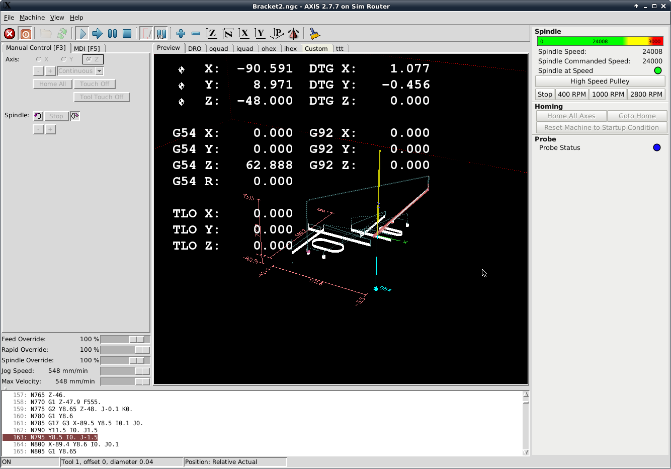
Now to the problem: I have a diy built router and thought as a good start off project I would cut a bracket out of a bit of rectangular hollow section. I have drawn my part in Fusion, generated the Gcode for LinuxCNC, homed my axes (x,y and z at machine 0), touched off the part in the lower left corner and set this as G54 (0,0,0). I then load my code and press run. Unfortunately an error occurs along the line of the code exceeds soft limits in the z axis. I press proceed anyway and the tool tip moves to part 0,0,0. Then it stops and the "Linear move on line 68 would exceed joint 2's positive limit" error is displayed (see attached screenshot).
Axis 2 is obviously a reference to the z axis as defined in the ini file (see attached at the bottom). But whats even more confusing is that the line specified doesn't even refer to the z axis, it refers to the x axis.
I have looked at all the extents of the part and they are well within the machine limits. However as can be seen in the screenshot, an additional move is shown (in blue) from the G54 icon (which as far as I am aware should be the 0,0,0 location and should be directly below that point where the triad is). And I cannot work out where this additional move has come from.
I have also been told that the N20 line is missing the G53 command. I have looked at this and in either case (with or without the G53 command) the same problem occurs.
Can anyone assist me? Any help is greatly appreciated.
My setup uses:
x axis is from -530 to +530 with home position at 0,
y axis is from -422.5 to +422.5, with home position at 0, and
z axis is from -150 (at table) to 0.1 (at max extent), with home position at 0
Some general items that may be useful:
CAD/CAM: Fusion 360
CNC software: LinuxCNC (aka EMC2)
no home switches
no limit switches
I have attached a screenshot of whats happening, the ini file and the g code for the bracket.
Keep in mind that I am relatively new to all this. I have some limited experience with Linux and generally understand what's going on but this has me stumped. Its probably glaringly obvious!
Thanks for your help.
First off, I am not sure if this is in the right area or not as I have never really posted anything here.
I have seen several posts on here and other forums relating to this but cant seem to get a straight answer on how to fix it or the fix doesn't work for my machine.
Now to the problem: I have a diy built router and thought as a good start off project I would cut a bracket out of a bit of rectangular hollow section. I have drawn my part in Fusion, generated the Gcode for LinuxCNC, homed my axes (x,y and z at machine 0), touched off the part in the lower left corner and set this as G54 (0,0,0). I then load my code and press run. Unfortunately an error occurs along the line of the code exceeds soft limits in the z axis. I press proceed anyway and the tool tip moves to part 0,0,0. Then it stops and the "Linear move on line 68 would exceed joint 2's positive limit" error is displayed (see attached screenshot).
Axis 2 is obviously a reference to the z axis as defined in the ini file (see attached at the bottom). But whats even more confusing is that the line specified doesn't even refer to the z axis, it refers to the x axis.
I have looked at all the extents of the part and they are well within the machine limits. However as can be seen in the screenshot, an additional move is shown (in blue) from the G54 icon (which as far as I am aware should be the 0,0,0 location and should be directly below that point where the triad is). And I cannot work out where this additional move has come from.
I have also been told that the N20 line is missing the G53 command. I have looked at this and in either case (with or without the G53 command) the same problem occurs.
Can anyone assist me? Any help is greatly appreciated.
My setup uses:
x axis is from -530 to +530 with home position at 0,
y axis is from -422.5 to +422.5, with home position at 0, and
z axis is from -150 (at table) to 0.1 (at max extent), with home position at 0
Some general items that may be useful:
CAD/CAM: Fusion 360
CNC software: LinuxCNC (aka EMC2)
no home switches
no limit switches
I have attached a screenshot of whats happening, the ini file and the g code for the bracket.
Keep in mind that I am relatively new to all this. I have some limited experience with Linux and generally understand what's going on but this has me stumped. Its probably glaringly obvious!
Thanks for your help.
Please Log in or Create an account to join the conversation.
- verticalperformance
-
- Offline
- Senior Member
-

Less
More
- Posts: 55
- Thank you received: 11
26 Jun 2017 07:22 - 28 Jun 2017 08:20 #94956
by verticalperformance
Replied by verticalperformance on topic Linear movement exceeding joint 2's positive limit in LinuxCNC
Usually its a problem with the length of the tool defined in the tool table.
I generally get this problem when drilling as the drill length uses a lot of the Z space, and sometime the sum of the setup and tool length will exceed the soft limits.
Load Tool 1, then do a T1 M6 G43 in the MDI tab
Touch off Z again and see if that improves things.
The G53 tells the machine to moveto in machine coordinates (ie G53 G0 Z0 will move the z axis to the z=0 home location)
As the N20 line seems to be intended to be "go to Z home when starting" the G53 would probably be appropriate - the machine will move up home.
N30 then tells the machine to load tool #1 (or if the manual tool changer is used it will prompt the user to change tool), again that would make sense to have the Z as far up as it could go to make it easy to load the tool.
N60 applies a tool length offset for tool#1 using the G43 and then moves the tool tip to Z=15mm including the tool length offset. I suspect this is where the issue is.
Touching off z=0 with Tool#1 and G43 active should essentially ignore any issues with having the offset in the tool table incorrect.
Have a look in the documentation about Tool Compensation www.linuxcnc.org/docs/2.7/html/gcode/tool-compensation.html
The .ini file looks like the machine is configured in mm, but the tool details you can see in the screen grab status bar in axis look to be in inches, maybe there is an issue there? .125 is a pretty small metric cutter")
Took me a while to get my head around tool length compensation, and I still stuff it up regularly. Wait till you try tool diameter compensation!
I generally get this problem when drilling as the drill length uses a lot of the Z space, and sometime the sum of the setup and tool length will exceed the soft limits.
Load Tool 1, then do a T1 M6 G43 in the MDI tab
Touch off Z again and see if that improves things.
The G53 tells the machine to move
As the N20 line seems to be intended to be "go to Z home when starting" the G53 would probably be appropriate - the machine will move up home.
N30 then tells the machine to load tool #1 (or if the manual tool changer is used it will prompt the user to change tool), again that would make sense to have the Z as far up as it could go to make it easy to load the tool.
N60 applies a tool length offset for tool#1 using the G43 and then moves the tool tip to Z=15mm including the tool length offset. I suspect this is where the issue is.
Touching off z=0 with Tool#1 and G43 active should essentially ignore any issues with having the offset in the tool table incorrect.
Have a look in the documentation about Tool Compensation www.linuxcnc.org/docs/2.7/html/gcode/tool-compensation.html
The .ini file looks like the machine is configured in mm, but the tool details you can see in the screen grab status bar in axis look to be in inches, maybe there is an issue there? .125 is a pretty small metric cutter
Took me a while to get my head around tool length compensation, and I still stuff it up regularly. Wait till you try tool diameter compensation!
Last edit: 28 Jun 2017 08:20 by verticalperformance.
The following user(s) said Thank You: BeachBum, DPFlex
Please Log in or Create an account to join the conversation.
- tommylight
-

- Offline
- Moderator
-

Less
More
- Posts: 21762
- Thank you received: 7436
26 Jun 2017 08:53 #94963
by tommylight
Replied by tommylight on topic Linear movement exceeding joint 2's positive limit in LinuxCNC
First check the min_limit and max_limit for joint.2. (Z axis). Depending on your setup, it should be usualy set up to something like +50 max and -100 min in milimeters. That is also dependant on the cam software and offsets and tool length sensor and compensation.
The simplest way of using it is to set it as mentioned above, move the tool down to where it actualy touches the top surface of the material, home Z axis, and run the code. That would assume the gcode is set to go deep only as much as the machine could handle.
You could try the splash code in Linuxcnc as it is set to go 0.125 mm deep, but you should double check that as it was a long time ago since i used the splash for testing.
The following user(s) said Thank You: BeachBum
Please Log in or Create an account to join the conversation.
- BeachBum
- Offline
- New Member
-
Less
More
- Posts: 8
- Thank you received: 0
01 Jul 2017 06:55 #95262
by BeachBum
Replied by BeachBum on topic Linear movement exceeding joint 2's positive limit in LinuxCNC
Thanks verticalperformance. I never knew but there were example tools already in the tool table. Even though I had a tool 1 it was picking a different tool 1 that was an example set in inches.
Unfortunately that didn't solve the issue. So you say that I should:
1. set my home location
2. load my tool (physically and then enter T1 M6) in G53
3. attach my workpiece and zero the workpiece in G54
4. load my code and run
??
Unfortunately that didn't solve the issue. So you say that I should:
1. set my home location
2. load my tool (physically and then enter T1 M6) in G53
3. attach my workpiece and zero the workpiece in G54
4. load my code and run
??
Please Log in or Create an account to join the conversation.
- verticalperformance
-
- Offline
- Senior Member
-
Less
More
- Posts: 55
- Thank you received: 11
02 Jul 2017 10:22 #95274
by verticalperformance
Replied by verticalperformance on topic Linear movement exceeding joint 2's positive limit in LinuxCNC
If your router holds its tool using a collet where the distance between the end of the tool tip and the spindle is not constant when you change tools (which would be typical for a router) there is very little benefit in having Z offset length's of anything other than zero in the tool table. You are forced to touch off the Z each time you change the tool regardless. Likewise there is pretty well no point in having more than one tool referenced in the g-code file either - have a separate g-code file for each tool needed. So the T1 M6 G43 codes are redundant in this case.
Before I started using the tool table and tools in holders this is how I did it.
Make sure all the tools in the tool table have no Z-offset
Home the Machine
Mount the tool in the spindle
Mount the workpiece to the bed
Touch off x then y to known location on workpiece
Touch off tool tip to known Z on workpiece
Load code and run.
Basically exactly what you said.
When you look at your screen plot, the z envelope is 172.3mm, however your z axis travel is only 150mm, that is why the error is there. But why?
I took my sim-mill .ini file and changed the axis travel limits to match yours, and loaded your g-code and only get a z envelope of 77.9, and hence the code runs in the sim....
Only thing that is different is I have my Z home at the top of the motion, so Z travels from 0 to 150, with the home location at Z=150
I made a new tool #1 in my tool table with Z=0 offset and diameter=.040 (my sim is in inches)
One thing I notice is that I don't see that big Z move and rapid through the G54 that you can see in your screen grab (the additional move you are trying to figure out!) Before running the code, click in the backplot on the Z move prior to the rapid in X and see what line number is highlighted.
I still don't know what the issue is - suspect tool table and touch off?
Keith
Before I started using the tool table and tools in holders this is how I did it.
Make sure all the tools in the tool table have no Z-offset
Home the Machine
Mount the tool in the spindle
Mount the workpiece to the bed
Touch off x then y to known location on workpiece
Touch off tool tip to known Z on workpiece
Load code and run.
Basically exactly what you said.
When you look at your screen plot, the z envelope is 172.3mm, however your z axis travel is only 150mm, that is why the error is there. But why?
I took my sim-mill .ini file and changed the axis travel limits to match yours, and loaded your g-code and only get a z envelope of 77.9, and hence the code runs in the sim....
Only thing that is different is I have my Z home at the top of the motion, so Z travels from 0 to 150, with the home location at Z=150
#+ Third axis
[AXIS_2]

TYPE =                          LINEAR
HOME =                          150
...
MIN_LIMIT =                     0
MAX_LIMIT =                     150
...
HOME_OFFSET =                   150
...
I made a new tool #1 in my tool table with Z=0 offset and diameter=.040 (my sim is in inches)
One thing I notice is that I don't see that big Z move and rapid through the G54 that you can see in your screen grab (the additional move you are trying to figure out!) Before running the code, click in the backplot on the Z move prior to the rapid in X and see what line number is highlighted.
I still don't know what the issue is - suspect tool table and touch off?
Keith
Please Log in or Create an account to join the conversation.
- BeachBum
- Offline
- New Member
-
Less
More
- Posts: 8
- Thank you received: 0
09 Jul 2017 08:48 #95532
by BeachBum
Replied by BeachBum on topic Linear movement exceeding joint 2's positive limit in LinuxCNC
Well this has me stumped. I tried setting the z axis as per those limits and home offsets you mentioned Keith. This time it did exactly the same thing, except when it tried the "go to home" command it tried to dig into the table.
I tried half a dozen variations of home offsets and locations and all with the same result. And each time it is line 68 that occurs as the line that exceeds the boundaries.
I just cant work out what the big z move is.
I think i'm going to forget linuxcnc and give Mach a go.
Thanks for your help.
I tried half a dozen variations of home offsets and locations and all with the same result. And each time it is line 68 that occurs as the line that exceeds the boundaries.
I just cant work out what the big z move is.
I think i'm going to forget linuxcnc and give Mach a go.
Thanks for your help.
Please Log in or Create an account to join the conversation.
- verticalperformance
-
- Offline
- Senior Member
-
Less
More
- Posts: 55
- Thank you received: 11
10 Jul 2017 09:42 #95585
by verticalperformance
Replied by verticalperformance on topic Linear movement exceeding joint 2's positive limit in LinuxCNC
Can you attach the tool table for us to have a look at?
Per your ini file it will be named tool.tbl and should be in the same directory.
I also just noticed in your .ini file you have in the EMCIO section
TOOL_CHANGE_AT_G3 = 0
Per the docs this should be TOOL_CHANGE_AT_G30 = 0
Don't think this will fix, but never hurts to try. I don't have this line at all in mine so I suspect that is the same as =0
Try commenting it our with a # and see what happens?
I also see that you have remapped M6
REMAP=M6 modalgroup=6 ngc=tool-change
perhaps that is the issue - test by commenting out the remap lines in the .ini and even comment out any M6 lines in the g-code. If you are only using one tool you don't need a Tx M6 in your g-code unless you are using some form of tool compensation and the tool table.
I'm leaning towards whatever happens when you issue the M6 being the issue,
What is in the tool-change.ngc and tool-job-begin.ngc files (attache them too!) and do you need this stuff - seems pretty advanced config to me.
keith
Per your ini file it will be named tool.tbl and should be in the same directory.
I also just noticed in your .ini file you have in the EMCIO section
TOOL_CHANGE_AT_G3 = 0
Per the docs this should be TOOL_CHANGE_AT_G30 = 0
Don't think this will fix, but never hurts to try. I don't have this line at all in mine so I suspect that is the same as =0
Try commenting it our with a # and see what happens?
I also see that you have remapped M6
REMAP=M6 modalgroup=6 ngc=tool-change
perhaps that is the issue - test by commenting out the remap lines in the .ini and even comment out any M6 lines in the g-code. If you are only using one tool you don't need a Tx M6 in your g-code unless you are using some form of tool compensation and the tool table.
I'm leaning towards whatever happens when you issue the M6 being the issue,
[RS274NGC]
PARAMETER_FILE = linuxcnc.var
SUBROUTINE_PATH= /home/kieran/linuxcnc/configs/Mill/ManualToolChange
REMAP=M6 modalgroup=6 ngc=tool-change
REMAP=M600 modalgroup=6 ngc=tool-job-begin
What is in the tool-change.ngc and tool-job-begin.ngc files (attache them too!) and do you need this stuff - seems pretty advanced config to me.
keith
The following user(s) said Thank You: BeachBum
Please Log in or Create an account to join the conversation.
- BeachBum
- Offline
- New Member
-
Less
More
- Posts: 8
- Thank you received: 0
23 Jul 2017 08:30 - 26 Jul 2017 01:25 #96307
by BeachBum
Replied by BeachBum on topic Linear movement exceeding joint 2's positive limit in LinuxCNC
Thank you for all the suggestions. I have not had time to look at this for a while now but jumped onto it this afternoon.
So I started again from scratch without any of the added files or remaps. This has worked out fine the first half dozen trials I have undertaken. I must assume that there was something in there that was causing the very large move at the beginning. That was no longer seen with the new configuration.
One thing I did notice was that I had my lower limit set as -0.1. Using the new configuration a slightly different warning came up stating that the minimum limit was affected. I changed the z axis limits to be -70 and +80 and the problem no longer occurred. Ie if your part starts at 0 and extends to -50 on the zaxis and the axis 2 limit is -0.1 technically the part is outside the limits.
I never realised that the limits were applied to the workpiece coordinates. I assumed they were fixed at the world coordinates.
Im going to stick with this config for now.
I came back to this problem and found the actual reason for this: In the Remap code (Which I would like to keep as it greatly helps with locating the tool heights etc after a manual tool change), there is a line that specifies the coordinates of the tool change location. Of course I forgot to change these to coordinates within my limits! Hence why the large z axis move.
Thanks again for bearing with me and my stupid mistakes.
Last edit: 26 Jul 2017 01:25 by BeachBum. Reason: New understanding of problem
Please Log in or Create an account to join the conversation.
Time to create page: 0.219 seconds