Encoder Wiring on Mesa 7i77 board
- jwsigler
- Offline
- Senior Member
-

Less
More
- Posts: 63
- Thank you received: 1
06 Sep 2016 05:43 #80064
by jwsigler
Encoder Wiring on Mesa 7i77 board was created by jwsigler
I am progressing on my retrofit, but have hit a stumbling block on getting my encoders to work. The system is a Tree Journeyman 325 which I am retrofitting using a Mesa 5i25/7i77 setup. I can get the servos to react through Linuxcnc and move the table a little, but I instantly get a following error and the DRO does not show any movement of the axis. My guess is that I do not have the encoders wired up correctly even though I wired the encoders exactly how they were previously wired, which may be the problem.
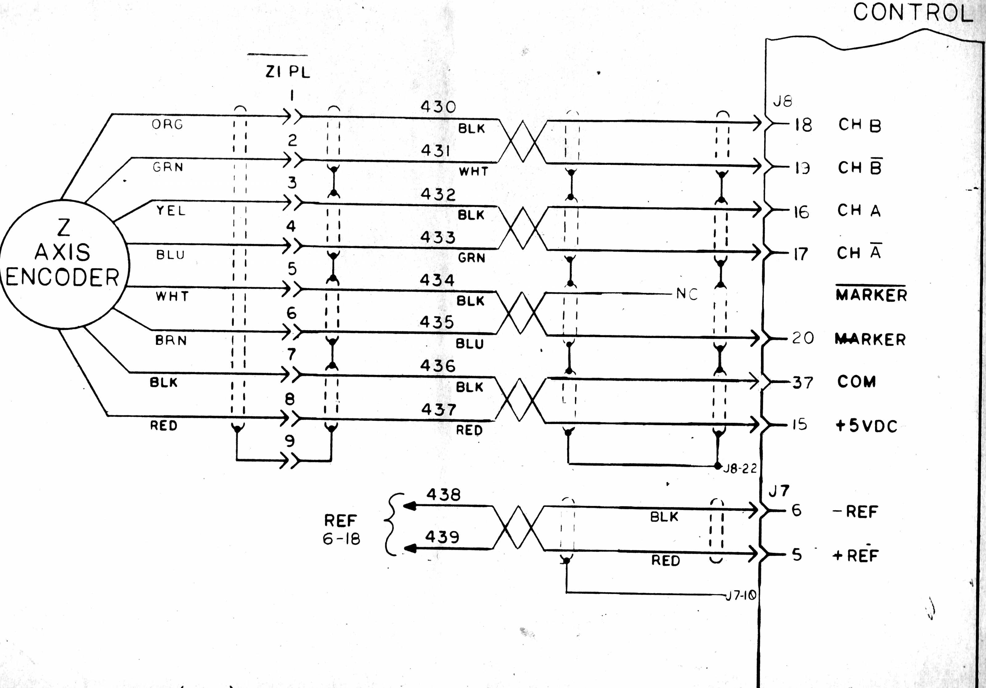
Following is a schematic of the encoder wiring from the original mill setup.
As can be seen, the Negative Marker wire was not hooked up on the original mill system so I did not hook it up on the new system. I assume it would correspond to /IDX0 on the Mesa 7i77 board and maybe it does need to be wired in. I also noticed that some of the wiring pairs have resistors across them. I left these alone, but maybe I should have removed them. My next step is to use a voltmeter to test some of the wiring pairs as describe in one of the other forum posts, but if anyone can tell me whether I need to hook up the Negative Marker wire and whether I should remove the resistors across the wiring pairs as shown in the old schematic, that would be appreciated.
Thanks.
Please Log in or Create an account to join the conversation.
- emcPT
-

- Offline
- Platinum Member
-

Less
More
- Posts: 695
- Thank you received: 138
06 Sep 2016 17:48 #80084
by emcPT
Replied by emcPT on topic Encoder Wiring on Mesa 7i77 board
Hello,
Best test is to move the motor and see if the encoder changes position (DRO changes position) with the machine down but the encoders and mesa board powered.
Why do you say that they have resistors? It looks the shielding representation. The marker should be the index, and you can connect the NOT INDEX also.
Please Log in or Create an account to join the conversation.
- jwsigler
- Offline
- Senior Member
-

Less
More
- Posts: 63
- Thank you received: 1
07 Sep 2016 02:52 #80109
by jwsigler
Replied by jwsigler on topic Encoder Wiring on Mesa 7i77 board
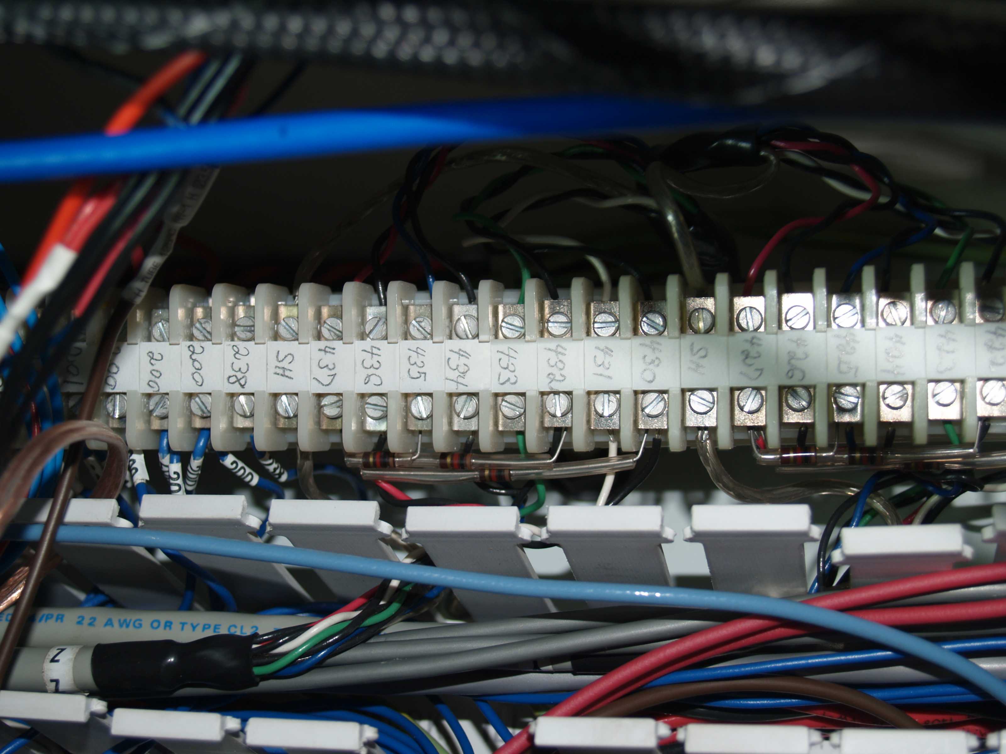
I do not know why, but there are resistors across some of the wiring pairs. It may not show in the schematic, but as can be seen in the following photo, there are resistors between 430 and 437, 432 and 437, and 435 and 437.
There are similar resistor pairs on all three sets of axis encoder wiring. I am hesitant about removing things like this because there must have been some reason for them in the first place. I had diodes mounted across all the coil terminals on my relays and eventually I found out that those were required as flyback diodes. Luckily I read about flyback diodes and knew not to remove them. I do not know if these resistors are something similar and that there should be resistors across all these pairings. Apparently each of these resistors ties the A channel, B channel, and the Marker (index) channel to the positive 5Vdc. I am hoping someone skilled in electronics can tell me if these are necessary, adn if not, would they be a reason why my 7i77 board does not appear to see any of the encoders. Of course these were required for the old Dynapath controller to work. I just do not know if they are required for a Mesa 7i77 to read my encoders.
There are similar resistor pairs on all three sets of axis encoder wiring. I am hesitant about removing things like this because there must have been some reason for them in the first place. I had diodes mounted across all the coil terminals on my relays and eventually I found out that those were required as flyback diodes. Luckily I read about flyback diodes and knew not to remove them. I do not know if these resistors are something similar and that there should be resistors across all these pairings. Apparently each of these resistors ties the A channel, B channel, and the Marker (index) channel to the positive 5Vdc. I am hoping someone skilled in electronics can tell me if these are necessary, adn if not, would they be a reason why my 7i77 board does not appear to see any of the encoders. Of course these were required for the old Dynapath controller to work. I just do not know if they are required for a Mesa 7i77 to read my encoders.
Please Log in or Create an account to join the conversation.
- emcPT
-

- Offline
- Platinum Member
-

Less
More
- Posts: 695
- Thank you received: 138
07 Sep 2016 06:34 #80116
by emcPT
Replied by emcPT on topic Encoder Wiring on Mesa 7i77 board
It seams that the resistors are also pull ups? Are they not all connected to 5VDC?
They are probably more a "request" from your encoder rather than the controller. You can safely test with or without them on the 7i77.
They are probably more a "request" from your encoder rather than the controller. You can safely test with or without them on the 7i77.
Please Log in or Create an account to join the conversation.
- andypugh
-

- Offline
- Moderator
-

Less
More
- Posts: 23178
- Thank you received: 4866
07 Sep 2016 20:18 #80168
by andypugh
Replied by andypugh on topic Encoder Wiring on Mesa 7i77 board
Just to say: Having the index not wired correctly would only ever matter if you chose to use encoder index homing. It is not used at any other time.
(You should use encoder index homing, it makes your home positions as accurate as possible)
(You should use encoder index homing, it makes your home positions as accurate as possible)
Please Log in or Create an account to join the conversation.
- tommylight
-

- Away
- Moderator
-

Less
More
- Posts: 19550
- Thank you received: 6566
07 Sep 2016 20:52 #80178
by tommylight
Replied by tommylight on topic Encoder Wiring on Mesa 7i77 board
Just had a look at it, they are pull up resistors. That must be due to encoders having "open collector" outputs.
For info on should you use them or remove them, that would be better answered from someone else, as i am not sure if the 7i77 board has them or not. I am sure it will work with them on, even if the 7i77 has them.
For info on should you use them or remove them, that would be better answered from someone else, as i am not sure if the 7i77 board has them or not. I am sure it will work with them on, even if the 7i77 has them.
Please Log in or Create an account to join the conversation.
- jwsigler
- Offline
- Senior Member
-

Less
More
- Posts: 63
- Thank you received: 1
08 Sep 2016 01:38 - 08 Sep 2016 16:27 #80199
by jwsigler
Replied by jwsigler on topic Encoder Wiring on Mesa 7i77 board
Thanks for the help but I think the problem is in the MESA 7i77 board. I have been checking the continuity of all my encoder wiring to make sure I have everything hooked up and I happened to check the continuity between the +5Vdc terminal on Encoder0 and the ground terminal on Encoder0 of the Mesa 7i77 board and the two are shorted. After that I checked the power and ground terminals on all six of the encoder terminal blocks on the Mesa 7i77 board and for all the encoders the power terminals are shorted to ground. This does not seem normal to me so I will need to contact Mesa to figure out the problem before continuing.
Last edit: 08 Sep 2016 16:27 by jwsigler.
Please Log in or Create an account to join the conversation.
- PCW
-

- Away
- Moderator
-

Less
More
- Posts: 18011
- Thank you received: 4847
08 Sep 2016 03:09 - 08 Sep 2016 03:42 #80205
by PCW
Replied by PCW on topic Encoder Wiring on Mesa 7i77 boardPlease return tha
There is _no_ question that you damaged the card initially, reverse protection diodes
dont just fail (along with both driver chips on the same power rail)
The driver chips passed a digital loopback at 24V but on further examination did not swing fully to 24V
so this was missed on the first return.
If 5V and ground are truly shorted its likely you damaged the 5V side of the card also
I was kind enough to repair a card that had been abused as a warranty repair, I will not do it again
Last edit: 08 Sep 2016 03:42 by PCW.
Please Log in or Create an account to join the conversation.
Moderators: PCW, jmelson
Time to create page: 0.121 seconds


