SSerial on 7i47 ... does a known working configuration exist?
- jCandlish
-
 Topic Author
- Offline
- Senior Member
-

Less
More
- Posts: 77
- Thank you received: 4
11 Feb 2017 13:06 #87813
by jCandlish
SSerial on 7i47 ... does a known working configuration exist? was created by jCandlish
I have successfully flashed my combined encoder+sserial bitfile to my 7i80 card, but the attached sserial devices are not recognized.
Does any working configuration of SSerial exist for the 7i47???
Does any working configuration of SSerial exist for the 7i47???
latheoperator@125cnc:/lib/firmware/hm2/7i80hd16$ mesaflash --verbose --device 7i80 --addr 10.100.10.100 --sserial
SSLBP port 0:
  SSLBP Version: 1.43
  SSLBP Channels: 2
  SSLBP Baud Rate: 2500000
  interface type: 12
  interface width: 8
  SSLBP Channel Start: 112
  SSLBP Channel Stride: 50
  SSLBP Processor Type: d8
  SSLBP Clock: 100 MHz
latheoperator@125cnc:/lib/firmware/hm2/7i80hd16$
latheoperator@125cnc:/lib/firmware/hm2/7i80hd16$ mesaflash --verbose --device 7i80 --addr 10.100.10.100 --readhmid
Configuration Name: HOSTMOT2
General configuration information:
BoardName : MESA7I80
FPGA Size: 16 KGates
FPGA Pins: 256
Number of IO Ports: 3
Width of one I/O port: 24
Clock Low frequency: 100.0000 MHz
Clock High frequency: 200.0000 MHz
IDROM Type: 3
Instance Stride 0: 4
Instance Stride 1: 64
Register Stride 0: 256
Register Stride 1: 256
Modules in configuration:
Module: WatchDog
There are 1 of WatchDog in configuration
Version: 0
Registers: 3
BaseAddress: 0C00
ClockFrequency: 100.000 MHz
Register Stride: 256 bytes
Instance Stride: 4 bytes
Module: MuxedQCount
There are 6 of MuxedQCount in configuration
Version: 3
Registers: 5
BaseAddress: 3500
ClockFrequency: 100.000 MHz
Register Stride: 256 bytes
Instance Stride: 4 bytes
Module: MuxedQCountSel
There are 1 of MuxedQCountSel in configuration
Version: 0
Registers: 0
BaseAddress: 0000
ClockFrequency: 100.000 MHz
Register Stride: 256 bytes
Instance Stride: 4 bytes
Module: PWM
There are 6 of PWM in configuration
Version: 0
Registers: 5
BaseAddress: 4000
ClockFrequency: 200.000 MHz
Register Stride: 256 bytes
Instance Stride: 4 bytes
Module: SSerial
There are 1 of SSerial in configuration
Version: 0
Registers: 6
BaseAddress: 5A00
ClockFrequency: 100.000 MHz
Register Stride: 256 bytes
Instance Stride: 64 bytes
Module: LED
There are 1 of LED in configuration
Version: 0
Registers: 1
BaseAddress: 0200
ClockFrequency: 100.000 MHz
Register Stride: 256 bytes
Instance Stride: 4 bytes
Module: IOPort
There are 3 of IOPort in configuration
Version: 0
Registers: 5
BaseAddress: 1000
ClockFrequency: 100.000 MHz
Register Stride: 256 bytes
Instance Stride: 4 bytes
Module: QCount
There are 12 of QCount in configuration
Version: 2
Registers: 5
BaseAddress: 3000
ClockFrequency: 100.000 MHz
Register Stride: 256 bytes
Instance Stride: 4 bytes
Configuration pin-out:
IO Connections for P1
Pin# I/O Pri. func Sec. func Chan Pin func Pin Dir
1 0 IOPort PWM 0 /Enable (Out)
3 1 IOPort MuxedQCount 0 MuxQ-A (In)
5 2 IOPort MuxedQCount 0 MuxQ-B (In)
7 3 IOPort MuxedQCount 0 MuxQ-IDX (In)
9 4 IOPort MuxedQCount 1 MuxQ-A (In)
11 5 IOPort MuxedQCount 1 MuxQ-B (In)
13 6 IOPort MuxedQCount 1 MuxQ-IDX (In)
15 7 IOPort MuxedQCount 2 MuxQ-A (In)
17 8 IOPort MuxedQCount 2 MuxQ-B (In)
19 9 IOPort MuxedQCount 2 MuxQ-IDX (In)
21 10 IOPort MuxedQCountSel 0 MuxSel0 (Out)
23 11 IOPort PWM 0 PWM (Out)
25 12 IOPort PWM 0 Dir (Out)
27 13 IOPort PWM 1 PWM (Out)
29 14 IOPort PWM 1 Dir (Out)
31 15 IOPort PWM 2 PWM (Out)
33 16 IOPort PWM 2 Dir (Out)
35 17 IOPort PWM 3 PWM (Out)
37 18 IOPort PWM 3 Dir (Out)
39 19 IOPort PWM 4 PWM (Out)
41 20 IOPort PWM 4 Dir (Out)
43 21 IOPort PWM 5 PWM (Out)
45 22 IOPort PWM 5 Dir (Out)
47 23 IOPort PWM 0 /Enable (Out)
IO Connections for P2
Pin# I/O Pri. func Sec. func Chan Pin func Pin Dir
1 24 IOPort None
3 25 IOPort None
5 26 IOPort None
7 27 IOPort None
9 28 IOPort SSerial 0 RXData1 (In)
11 29 IOPort QCount 1 Quad-A (In)
13 30 IOPort SSerial 0 RXData2 (In)
15 31 IOPort QCount 1 Quad-B (In)
17 32 IOPort None
19 33 IOPort QCount 1 Quad-IDX (In)
21 34 IOPort QCount 0 Quad-A (In)
23 35 IOPort QCount 2 Quad-A (In)
25 36 IOPort QCount 0 Quad-B (In)
27 37 IOPort QCount 2 Quad-B (In)
29 38 IOPort QCount 0 Quad-IDX (In)
31 39 IOPort QCount 2 Quad-IDX (In)
33 40 IOPort None
35 41 IOPort None
37 42 IOPort None
39 43 IOPort None
41 44 IOPort SSerial 0 TXData1 (Out)
43 45 IOPort SSerial 0 TXData2 (Out)
45 46 IOPort None
47 47 IOPort None
IO Connections for P3
Pin# I/O Pri. func Sec. func Chan Pin func Pin Dir
1 48 IOPort None
3 49 IOPort None
5 50 IOPort None
7 51 IOPort None
9 52 IOPort None
11 53 IOPort None
13 54 IOPort None
15 55 IOPort None
17 56 IOPort None
19 57 IOPort None
21 58 IOPort None
23 59 IOPort None
25 60 IOPort None
27 61 IOPort None
29 62 IOPort None
31 63 IOPort None
33 64 IOPort None
35 65 IOPort None
37 66 IOPort None
39 67 IOPort None
41 68 IOPort None
43 69 IOPort None
45 70 IOPort None
47 71 IOPort None
latheoperator@125cnc:/lib/firmware/hm2/7i80hd16$Please Log in or Create an account to join the conversation.
- PCW
-

- Offline
- Moderator
-

Less
More
- Posts: 17694
- Thank you received: 5174
11 Feb 2017 13:29 - 11 Feb 2017 13:48 #87816
by PCW
Replied by PCW on topic SSerial on 7i47 ... does a known working configuration exist?
sure, some have been used for many years
PIN_SSSVST2_2_4_7I47_72.vhd is an example pinout file
A pinout/ RS-422 polarity error is a likely cause of sserial not working
(since the 7I47 will have a somewhat weird RS-422 pinout)
I dug this out of an old email, might be helpful:
7I47 TXN- --> CAT5 ORANGE/WHITE
7I47 TXN+ --> CAT5 ORANGE
7I47 RXN- --> CAT5 GREEN/WHITE
7I47 RXN+ --> CAT5 GREEN
7I47 GND --> CAT5 BLUE BLUE/WHITE
7I47 +5 --> CAT5 BROWN BROWN/WHITE
Last edit: 11 Feb 2017 13:48 by PCW.
Please Log in or Create an account to join the conversation.
- jCandlish
-
Topic Author
- Offline
- Senior Member
-
Less
More
- Posts: 77
- Thank you received: 4
11 Feb 2017 15:17 #87822
by jCandlish
Replied by jCandlish on topic SSerial on 7i47 ... does a known working configuration exist?
OK, reflashed according to your muxed encoder recommendation, and rewired as above.
Still no SSerial device is detected.
on P4 of the 7i47 I have:
At this time I have only the 7i84 attached.
Ideas???
Still no SSerial device is detected.
IO Connections for P2
Pin#  I/O   Pri. func    Sec. func       Chan      Pin func        Pin Dir

 1     24   IOPort       None
 3     25   IOPort       None
 5     26   IOPort       None
 7     27   IOPort       None
 9     28   IOPort       SSerial          0        RXData1         (In)
11     29   IOPort       MuxedQCount      4        MuxQ-A          (In)
13     30   IOPort       SSerial          0        RXData2         (In)
15     31   IOPort       MuxedQCount      4        MuxQ-B          (In)
17     32   IOPort       None
19     33   IOPort       MuxedQCount      4        MuxQ-IDX        (In)
21     34   IOPort       MuxedQCount      3        MuxQ-A          (In)
23     35   IOPort       MuxedQCount      5        MuxQ-A          (In)
25     36   IOPort       MuxedQCount      3        MuxQ-B          (In)
27     37   IOPort       MuxedQCount      5        MuxQ-B          (In)
29     38   IOPort       MuxedQCount      3        MuxQ-IDX        (In)
31     39   IOPort       MuxedQCount      5        MuxQ-IDX        (In)
33     40   IOPort       None
35     41   IOPort       None
37     42   IOPort       None
39     43   IOPort       None
41     44   IOPort       SSerial          0        TXData1         (Out)
43     45   IOPort       SSerial          0        TXData2         (Out)
45     46   IOPort       None
47     47   IOPort       None
on P4 of the 7i47 I have:
pin    cat5 color       function
1      green            RX0
2      green/white      /RX0
6      br+br/white      +5
19     orange           TX0
20     orange/white     /TX0
21     bl+bl/white      GND
At this time I have only the 7i84 attached.
latheoperator@125cnc:/lib/firmware/hm2/7i80hd16$  mesaflash --verbose --device 7i80 --addr 10.100.10.100 --sserial
SSLBP port 0:
  SSLBP Version: 1.43
  SSLBP Channels: 2
  SSLBP Baud Rate: 2500000
  interface type: 12
  interface width: 8
  SSLBP Channel Start: 112
  SSLBP Channel Stride: 50
  SSLBP Processor Type: d8
  SSLBP Clock: 100 MHz
latheoperator@125cnc:/lib/firmware/hm2/7i80hd16$
Ideas???
Please Log in or Create an account to join the conversation.
- PCW
-
- Offline
- Moderator
-
Less
More
- Posts: 17694
- Thank you received: 5174
11 Feb 2017 15:58 #87823
by PCW
Replied by PCW on topic SSerial on 7i47 ... does a known working configuration exist?
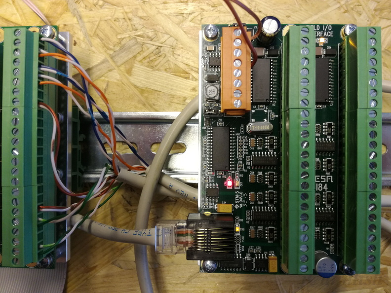
Does the 7I84 have field power applied? (do you get a red light when not running?)
Please Log in or Create an account to join the conversation.
- jCandlish
-
Topic Author
- Offline
- Senior Member
-
Less
More
- Posts: 77
- Thank you received: 4
11 Feb 2017 16:11 #87824
by jCandlish
Replied by jCandlish on topic SSerial on 7i47 ... does a known working configuration exist?
Yes
+12 volts at pin 5 VIN field power
0 volts at 8 pin 8 GND field power
Jumper W1 is in positioned to the right for separate VIN.
CR2 is illuminated yellow
CR6 is illuminated red
CR8 is illuminated yellow
I have also tried connecting to the 7i73. None of its LEDs illuminate.
+12 volts at pin 5 VIN field power
0 volts at 8 pin 8 GND field power
Jumper W1 is in positioned to the right for separate VIN.
CR2 is illuminated yellow
CR6 is illuminated red
CR8 is illuminated yellow
I have also tried connecting to the 7i73. None of its LEDs illuminate.
Please Log in or Create an account to join the conversation.
- PCW
-
- Offline
- Moderator
-
Less
More
- Posts: 17694
- Thank you received: 5174
11 Feb 2017 16:13 #87825
by PCW
Replied by PCW on topic SSerial on 7i47 ... does a known working configuration exist?
if none of the 7I73 LEDS illuminate, that suggest an electrical problem
(you should always get the RED fault LED if no communuications are occuring)
(you should always get the RED fault LED if no communuications are occuring)
Please Log in or Create an account to join the conversation.
- jCandlish
-
Topic Author
- Offline
- Senior Member
-
Less
More
- Posts: 77
- Thank you received: 4
11 Feb 2017 16:21 #87826
by jCandlish
OK. Not good.
The 7i73 is in-op when connected with either CAT5 cable.
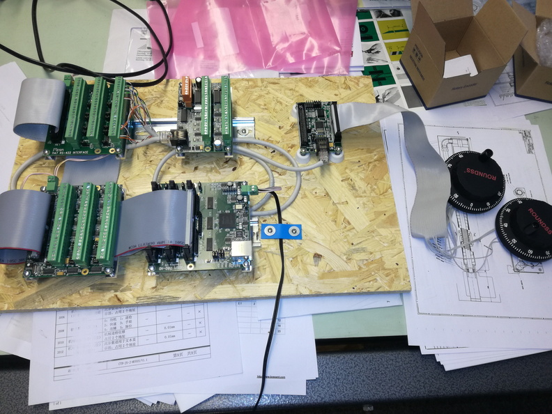
I've got a pretty simple breadboard setup. Nothing obvious looks bad.
Vcc is 5.24 with 20mV ripple.
Replied by jCandlish on topic SSerial on 7i47 ... does a known working configuration exist?
if none of the 7I73 LEDS illuminate, that suggest an electrical problem
OK. Not good.
The 7i73 is in-op when connected with either CAT5 cable.
I've got a pretty simple breadboard setup. Nothing obvious looks bad.
Vcc is 5.24 with 20mV ripple.
Please Log in or Create an account to join the conversation.
- jCandlish
-
Topic Author
- Offline
- Senior Member
-
Less
More
- Posts: 77
- Thank you received: 4
12 Feb 2017 09:22 - 12 Feb 2017 09:23 #87865
by jCandlish
Replied by jCandlish on topic SSerial on 7i47 ... does a known working configuration exist?
It turns out that the old Sun Microsystems ethernet patchcable from the junk box uses non-standard wire colors. Crazy!
All is good with a different patchcable.
Thanks for your help!
All is good with a different patchcable.
latheoperator@125cnc:/lib/firmware/hm2/7i80hd16$ mesaflash --verbose --device 7i80 --addr 10.100.10.100 --sserial
SSLBP port 0:
  SSLBP Version: 1.43
  SSLBP Channels: 2
  SSLBP Baud Rate: 2500000
  interface type: 12
  interface width: 8
  SSLBP Channel Start: 112
  SSLBP Channel Stride: 50
  SSLBP Processor Type: d8
  SSLBP Clock: 100 MHz
  sserial device at channel 0: 7I73
    Contrast = ffff [16 bits UNSIGNED OUT | UNIT: None | RANGE: 0.00 - 0.00 | ADDR: 09C6]
    EncMode0 = ffff [16 bits UNSIGNED OUT | UNIT: None | RANGE: 0.00 - 0.00 | ADDR: 0998]
    EncMode1 = ffff [16 bits UNSIGNED OUT | UNIT: None | RANGE: 0.00 - 0.00 | ADDR: 099A]
    EncMode2 = ffff [16 bits UNSIGNED OUT | UNIT: None | RANGE: 0.00 - 0.00 | ADDR: 099C]
    EncMode3 = ffff [16 bits UNSIGNED OUT | UNIT: None | RANGE: 0.00 - 0.00 | ADDR: 099E]
    SwRevision = 14
    HwRevision = 1
    KeyMode = ffff [16 bits UNSIGNED OUT | UNIT: None | RANGE: 0.00 - 0.00 | ADDR: 09DE]
    NVContrast = 2710 [16 bits NV UNSIGNED OUT | UNIT: None | RANGE: 0.00 - 0.00 | ADDR: 0044]
    NVEncMode0 = 0 [16 bits NV UNSIGNED OUT | UNIT: None | RANGE: 0.00 - 0.00 | ADDR: 003A]
    NVEncMode1 = 0 [16 bits NV UNSIGNED OUT | UNIT: None | RANGE: 0.00 - 0.00 | ADDR: 003C]
    NVEncMode2 = 0 [16 bits NV UNSIGNED OUT | UNIT: None | RANGE: 0.00 - 0.00 | ADDR: 003E]
    NVEncMode3 = 0 [16 bits NV UNSIGNED OUT | UNIT: None | RANGE: 0.00 - 0.00 | ADDR: 0040]
    NVDispMode = 414 [16 bits NV UNSIGNED OUT | UNIT: None | RANGE: 0.00 - 0.00 | ADDR: 0006]
    NVKeyTimer = 1e [16 bits NV UNSIGNED OUT | UNIT: None | RANGE: 0.00 - 0.00 | ADDR: 0046]
    NVAnalogFilter = 8000 [16 bits NV UNSIGNED OUT | UNIT: None | RANGE: 0.00 - 0.00 | ADDR: 0042]
    NVBaudRate = 2.5Mb
    NVUnitNumber = 0x130000E2
    NVWatchDogTimeout = 50ms
    SOFTWARE MODE InputOutputEncoder [index 00]
    SOFTWARE MODE InputOutputEncoderAnalog [index 01]
    SOFTWARE MODE InputOutputEncoderAnalog [index 02]
    SOFTWARE MODE InputOutputEncoderDisplay [index 00]
    SOFTWARE MODE InputOutputEncoderAnalogDisplay [index 01]
    SOFTWARE MODE InputOutputEncoderAnalogWideDisplay [index 02]
    SOFTWARE MODE InputOutputEncoderKeycode4by8 [index 00]
    SOFTWARE MODE InputOutputEncoderAnalogKeycode4by8 [index 01]
    SOFTWARE MODE InputOutputEncoderAnalogKeycode4by8 [index 02]
    SOFTWARE MODE InputOutputEncoderDisplayKeycode4by8 [index 00]
    SOFTWARE MODE InputOutputEncoderAnalogDisplayKeyCode4by8 [index 01]
    SOFTWARE MODE InputOutputEncoderAnalogWideDisplayKeyCode4by8 [index 02]
    SOFTWARE MODE InputOutputEncoderKeycode8by8 [index 00]
    SOFTWARE MODE InputOutputEncoderAnalogKeyCode8by8 [index 01]
    SOFTWARE MODE InputOutputEncoderAnalogKeyCode8by8 [index 02]
    SOFTWARE MODE InputOutputEncoderDisplayKeycode8by8 [index 00]
    SOFTWARE MODE InputOutputEncoderAnalogDisplayKeyCode8by8 [index 01]
    SOFTWARE MODE InputOutputEncoderAnalogWideDisplayKeyCode8by8 [index 02]
  sserial device at channel 1: 7I84
    SwRevision = 15
    HwRevision = 1
    NVBaudRate = 2.5Mb
    NVUnitNumber = 0x180000F3
    NVWatchDogTimeout = 50ms
    EncMode0 = ffff [16 bits UNSIGNED IN | UNIT: None | RANGE: 0.00 - 0.00 | ADDR: 0998]
    EncMode1 = ffff [16 bits UNSIGNED IN | UNIT: None | RANGE: 0.00 - 0.00 | ADDR: 099A]
    NVEncMode0 = 0 [16 bits NV UNSIGNED IN | UNIT: None | RANGE: 0.00 - 0.00 | ADDR: 0066]
    NVEncMode1 = 0 [16 bits NV UNSIGNED IN | UNIT: None | RANGE: 0.00 - 0.00 | ADDR: 0068]
    SOFTWARE MODE Input_Output [index 00]
    SOFTWARE MODE IO_Analog_FieldVoltage [index 01]
    SOFTWARE MODE IO_Encoder_Analog [index 02]
latheoperator@125cnc:/lib/firmware/hm2/7i80hd16$
Thanks for your help!
Last edit: 12 Feb 2017 09:23 by jCandlish.
Please Log in or Create an account to join the conversation.
Moderators: PCW, jmelson
Time to create page: 0.088 seconds