Mesa 7i98 Anything I / O Ethernet setup a BTS7960 and Encoder
29 Dec 2021 11:05 - 29 Dec 2021 11:44 #230211
by BigDo
I waited a long time for my Mesa 7i98 Anything I / O Ethernet controller card (not available from welectron for 4 months) then I ordered it from esurplus and 4 days later I received the card. This is my first Mesa card, and I have a few questions about it.
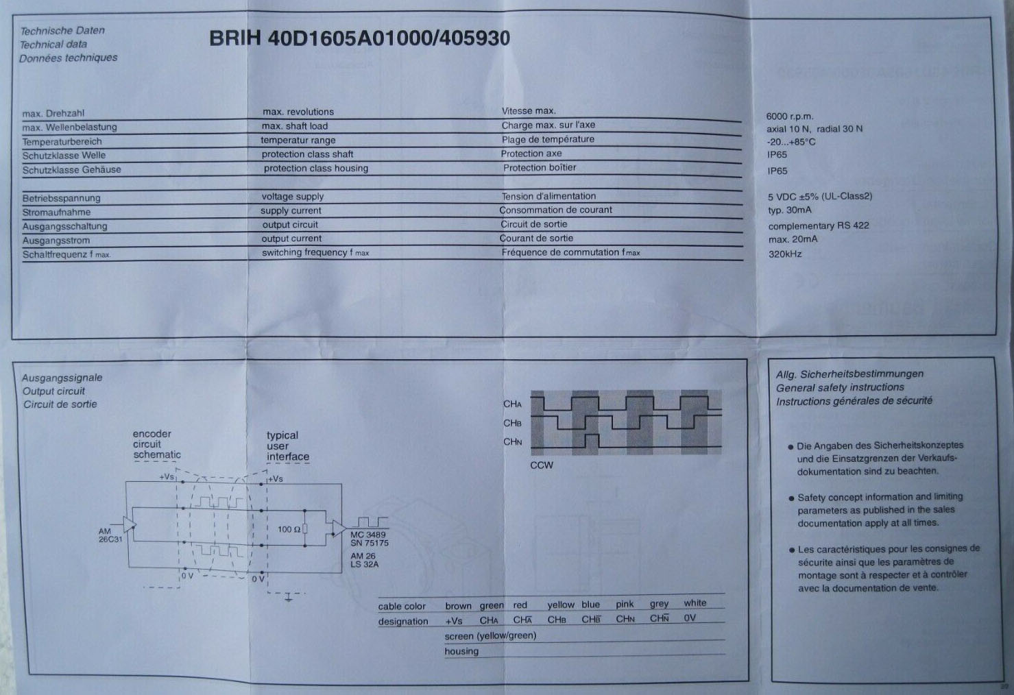
1. How do I setup and wire this encoder(BRIH-40D1605A1000)correctly?
brown + Vs
green ChA
red ChA
yellow ChB
blue ChB
pink ChN
gray ChN
white 0v
yell/gr screen
do I need 2 pins for each channel(A. B. N)?
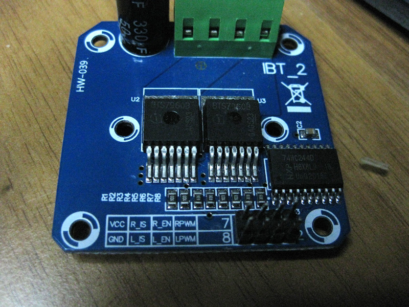
2. How do I setup and wire an IBT-2 (BTS7960) with the Mesa card?
Do I need 2 PWM pins (RPWM, LPWM) and 2 enable pins (R_EN, L_EN) per motor?
1. How do I setup and wire this encoder(BRIH-40D1605A1000)correctly?
brown + Vs
green ChA
red ChA
yellow ChB
blue ChB
pink ChN
gray ChN
white 0v
yell/gr screen
do I need 2 pins for each channel(A. B. N)?
2. How do I setup and wire an IBT-2 (BTS7960) with the Mesa card?
Do I need 2 PWM pins (RPWM, LPWM) and 2 enable pins (R_EN, L_EN) per motor?
Attachments:
Last edit: 29 Dec 2021 11:44 by BigDo.
Please Log in or Create an account to join the conversation.

30 Dec 2021 02:15 - 30 Dec 2021 02:16 #230308
by PCW
Replied by PCW on topic Mesa 7i98 Anything I / O Ethernet setup a BTS7960 and Encoder
That is a differential encoder, normally you would use a differential
input daughtercard for interfacing with this type of encoder but if you
connect it directly to a 7I98, you would only use one of each pair, that is,
only connect to:
CHA
CHB
CHN
+5V
GND
input daughtercard for interfacing with this type of encoder but if you
connect it directly to a 7I98, you would only use one of each pair, that is,
only connect to:
CHA
CHB
CHN
+5V
GND
Last edit: 30 Dec 2021 02:16 by PCW.
The following user(s) said Thank You: BigDo
Please Log in or Create an account to join the conversation.
30 Dec 2021 10:43 #230328
by BigDo
Replied by BigDo on topic Mesa 7i98 Anything I / O Ethernet setup a BTS7960 and Encoder
Thank you PCW.
the BTS7960 has R-PWM, L-PWM and 2 Enable pins,
is it the right way if I connect the 2 PWM pins together and switch the R-EN and L-EN with DIR signals?
the BTS7960 has R-PWM, L-PWM and 2 Enable pins,
is it the right way if I connect the 2 PWM pins together and switch the R-EN and L-EN with DIR signals?
Please Log in or Create an account to join the conversation.
30 Dec 2021 15:47 #230344
by PCW
Replied by PCW on topic Mesa 7i98 Anything I / O Ethernet setup a BTS7960 and Encoder
I would expect to drive the R-PWM and L-PWM pins with PWM outputs
with the PWM output type set to 2=up/down mode. The enables are
probably tied together and connected to a GPIO bit
NOTE: Directly connecting the FPGA outputs to a non-isolated driver chip
(with a common ground with the motor power supply) is quite likely
to damage the FPGA card unless you are very careful about EMI and ground
bumping. This also applies to the encoder connections. If you wish to do this,
at least add a 220 Ohm or so series resistor to each FPGA I/O pin to prevent
damage from negative voltage spikes
The following user(s) said Thank You: BigDo
Please Log in or Create an account to join the conversation.
30 Dec 2021 16:35 - 30 Dec 2021 16:58 #230348
by BigDo
Replied by BigDo on topic Mesa 7i98 Anything I / O Ethernet setup a BTS7960 and Encoder
i have i China-BOB with Oprocoupler installed for testing.
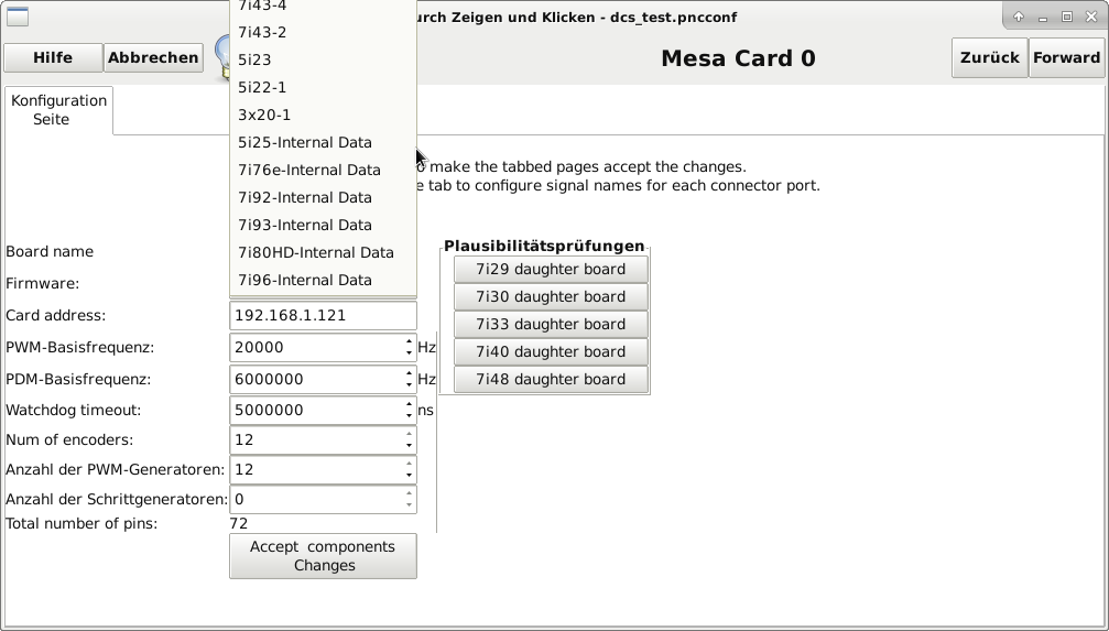
where do i set the PWM output type up, in linuxcnc or in the bitfile?
where do i set the PWM output type up, in linuxcnc or in the bitfile?
Last edit: 30 Dec 2021 16:58 by BigDo.
Please Log in or Create an account to join the conversation.
31 Dec 2021 13:32 #230388
by BigDo
Replied by BigDo on topic Mesa 7i98 Anything I / O Ethernet setup a BTS7960 and Encoder
PCW can you please take a look at my bitfile to see if I did everything right?
I have configured 4 PWM and 4 Encoder.I got some warnings during compilation, are they important?
I have configured 4 PWM and 4 Encoder.I got some warnings during compilation, are they important?
Attachments:
Please Log in or Create an account to join the conversation.
31 Dec 2021 15:58 - 31 Dec 2021 16:00 #230395
by D.L.
Replied by D.L. on topic Mesa 7i98 Anything I / O Ethernet setup a BTS7960 and Encoder
Duplicate index input for counter 2, no index input for counter 3.
IOPortTag & x"00" & NullTag & NullPin, -- I/O 17 PIN 1 just GPIO
IOPortTag & x"02" & QCountTag & QCountIdxPin, -- I/O 18 PIN 14 (Quad2 IDX)
IOPortTag & x"00" & NullTag & x"00", -- I/O 19 PIN 2
IOPortTag & x"03" & QCountTag & QCountQBPin, -- I/O 20 PIN 15 (Quad2 A)
IOPortTag & x"00" & NullTag & x"00", -- I/O 21 PIN 3
IOPortTag & x"03" & QCountTag & QCountQAPin, -- I/O 22 PIN 16 (Quad2 B )
IOPortTag & x"00" & NullTag & x"00", -- I/O 23 PIN 4
IOPortTag & x"02" & QCountTag & QCountIdxPin, -- I/O 24 PIN 17 (Quad2 IDX)
IOPortTag & x"00" & NullTag & x"00", -- I/O 25 PIN 5
IOPortTag & x"00" & NullTag & x"00", -- I/O 26 PIN 6
IOPortTag & x"00" & NullTag & x"00", -- I/O 27 PIN 7
IOPortTag & x"00" & NullTag & x"00", -- I/O 28 PIN 8
IOPortTag & x"00" & NullTag & x"00", -- I/O 29 PIN 9
IOPortTag & x"00" & NullTag & x"00", -- I/O 30 PIN 10
IOPortTag & x"00" & NullTag & x"00", -- I/O 31 PIN 11
IOPortTag & x"02" & QCountTag & QCountQAPin, -- I/O 32 PIN 12 (Quad2 A)
IOPortTag & x"02" & QCountTag & QCountQBPin, -- I/O 33 PIN 13 (Quad2 B )
Last edit: 31 Dec 2021 16:00 by D.L..
The following user(s) said Thank You: BigDo
Please Log in or Create an account to join the conversation.
02 Jan 2022 22:20 - 02 Jan 2022 22:26 #230578
by BigDo
Replied by BigDo on topic Mesa 7i98 Anything I / O Ethernet setup a BTS7960 and Encoder
finally i managed to flash my Mesa card, but the card does not appear in pncconf. How can I add the 7i98.
niko@dcs:~$ mesaflash --device 7i98 --readhmid
Configuration Name: HOSTMOT2

General configuration information:

  BoardName : MESA7I98
  FPGA Size: 9 KGates
  FPGA Pins: 144
  Number of IO Ports: 3
  Width of one I/O port: 17
  Clock Low frequency: 100.0000 MHz
  Clock High frequency: 200.0000 MHz
  IDROM Type: 3
  Instance Stride 0: 4
  Instance Stride 1: 64
  Register Stride 0: 256
  Register Stride 1: 256

Modules in configuration:

  Module: DPLL
  There are 1 of DPLL in configuration
  Version: 0
  Registers: 7
  BaseAddress: 7000
  ClockFrequency: 100.000 MHz
  Register Stride: 256 bytes
  Instance Stride: 4 bytes

  Module: WatchDog
  There are 1 of WatchDog in configuration
  Version: 0
  Registers: 3
  BaseAddress: 0C00
  ClockFrequency: 100.000 MHz
  Register Stride: 256 bytes
  Instance Stride: 4 bytes

  Module: IOPort
  There are 3 of IOPort in configuration
  Version: 0
  Registers: 5
  BaseAddress: 1000
  ClockFrequency: 100.000 MHz
  Register Stride: 256 bytes
  Instance Stride: 4 bytes

  Module: QCount
  There are 4 of QCount in configuration
  Version: 2
  Registers: 5
  BaseAddress: 3000
  ClockFrequency: 100.000 MHz
  Register Stride: 256 bytes
  Instance Stride: 4 bytes

  Module: PWM
  There are 8 of PWM in configuration
  Version: 0
  Registers: 5
  BaseAddress: 4100
  ClockFrequency: 200.000 MHz
  Register Stride: 256 bytes
  Instance Stride: 4 bytes

  Module: LED
  There are 1 of LED in configuration
  Version: 0
  Registers: 1
  BaseAddress: 0200
  ClockFrequency: 100.000 MHz
  Register Stride: 256 bytes
  Instance Stride: 4 bytes

Configuration pin-out:

IO Connections for P1
Pin#                  I/O   Pri. func    Sec. func       Chan      Pin func        Pin Dir

 1                      0   IOPort       None
14                      1   IOPort       QCount           0        Quad-IDX        (In)
 2                      2   IOPort       PWM              0        PWM             (Out)
15                      3   IOPort       QCount           1        Quad-A          (In)
 3                      4   IOPort       PWM              1        PWM             (Out)
16                      5   IOPort       QCount           1        Quad-B          (In)
 4                      6   IOPort       PWM              2        PWM             (Out)
17                      7   IOPort       QCount           1        Quad-IDX        (In)
 5                      8   IOPort       PWM              3        PWM             (Out)
 6                      9   IOPort       None
 7                     10   IOPort       None
 8                     11   IOPort       None
 9                     12   IOPort       None
10                     13   IOPort       None
11                     14   IOPort       None
12                     15   IOPort       QCount           0        Quad-A          (In)
13                     16   IOPort       QCount           0        Quad-B          (In)

IO Connections for P2
Pin#                  I/O   Pri. func    Sec. func       Chan      Pin func        Pin Dir

 1                     17   IOPort       None
14                     18   IOPort       QCount           2        Quad-IDX        (In)
 2                     19   IOPort       PWM              4        PWM             (Out)
15                     20   IOPort       QCount           3        Quad-B          (In)
 3                     21   IOPort       PWM              5        PWM             (Out)
16                     22   IOPort       QCount           3        Quad-A          (In)
 4                     23   IOPort       PWM              6        PWM             (Out)
17                     24   IOPort       QCount           3        Quad-IDX        (In)
 5                     25   IOPort       PWM              7        PWM             (Out)
 6                     26   IOPort       None
 7                     27   IOPort       None
 8                     28   IOPort       None
 9                     29   IOPort       None
10                     30   IOPort       None
11                     31   IOPort       None
12                     32   IOPort       QCount           2        Quad-A          (In)
13                     33   IOPort       QCount           2        Quad-B          (In)

IO Connections for P3
Pin#                  I/O   Pri. func    Sec. func       Chan      Pin func        Pin Dir

 1                     34   IOPort       None
14                     35   IOPort       None
 2                     36   IOPort       None
15                     37   IOPort       None
 3                     38   IOPort       None
16                     39   IOPort       None
 4                     40   IOPort       None
17                     41   IOPort       None
 5                     42   IOPort       None
 6                     43   IOPort       None
 7                     44   IOPort       None
 8                     45   IOPort       None
 9                     46   IOPort       None
10                     47   IOPort       None
11                     48   IOPort       None
12                     49   IOPort       None
13                     50   IOPort       None
Attachments:
Last edit: 02 Jan 2022 22:26 by BigDo.
Please Log in or Create an account to join the conversation.
Time to create page: 0.152 seconds