BOB wiring
13 Jul 2023 21:48 #275374
by Stef
Replied by Stef on topic BOB wiring
With the BOB connected to the Mesa card, I measured the voltage between HDR26 pin 10 and pin 23 (via the soldered pins on the underside of the Mesa card).
This is 5V, and activating the limit switch does not change this voltage. The limit switch is connected to pin 12 of the BOB.
With the BOB completely disconnected from the Mesa card I still measure this 5V between HDR26 pin 10 and pin 23.
The BOB is supplied with 5V.
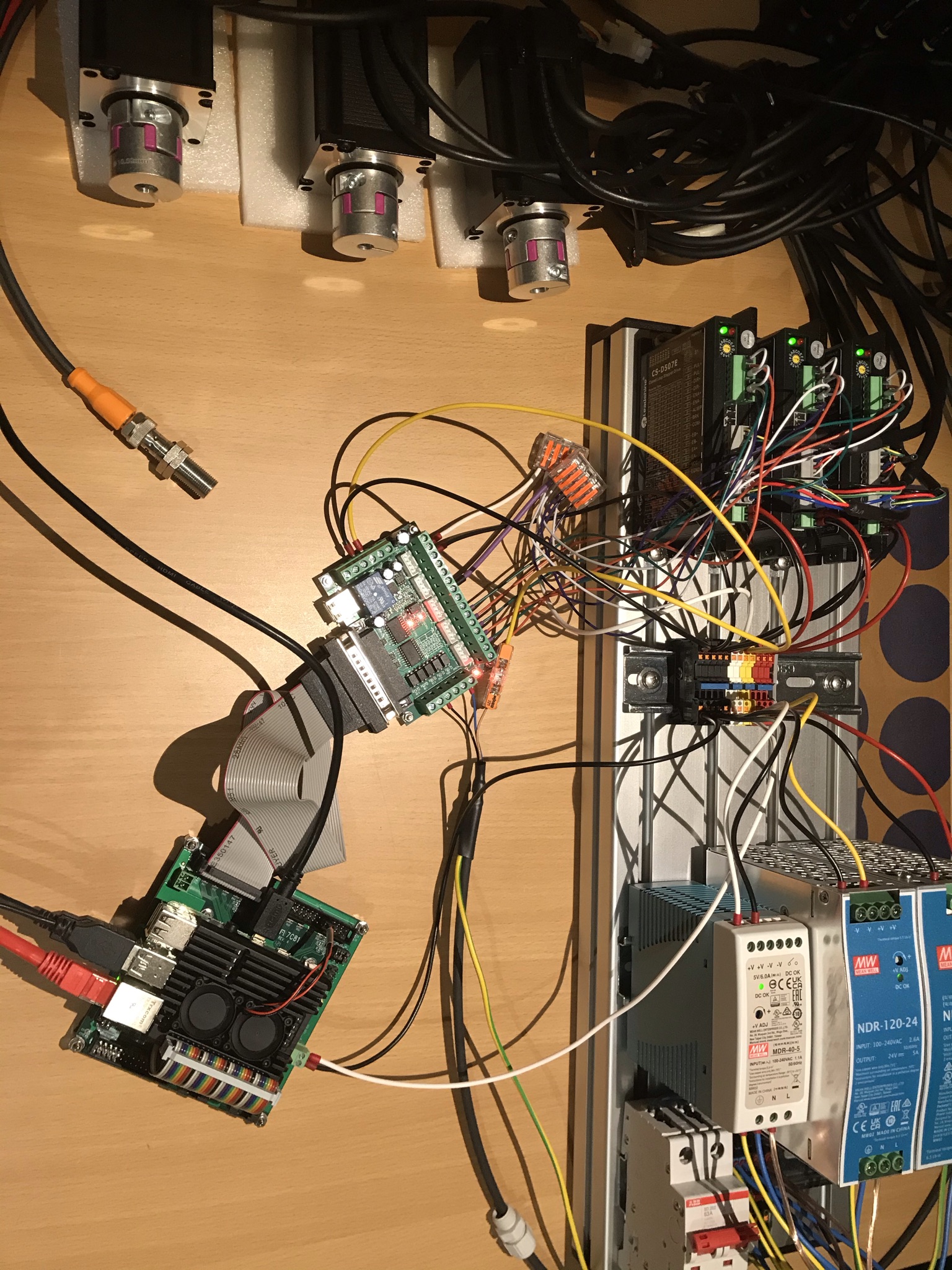
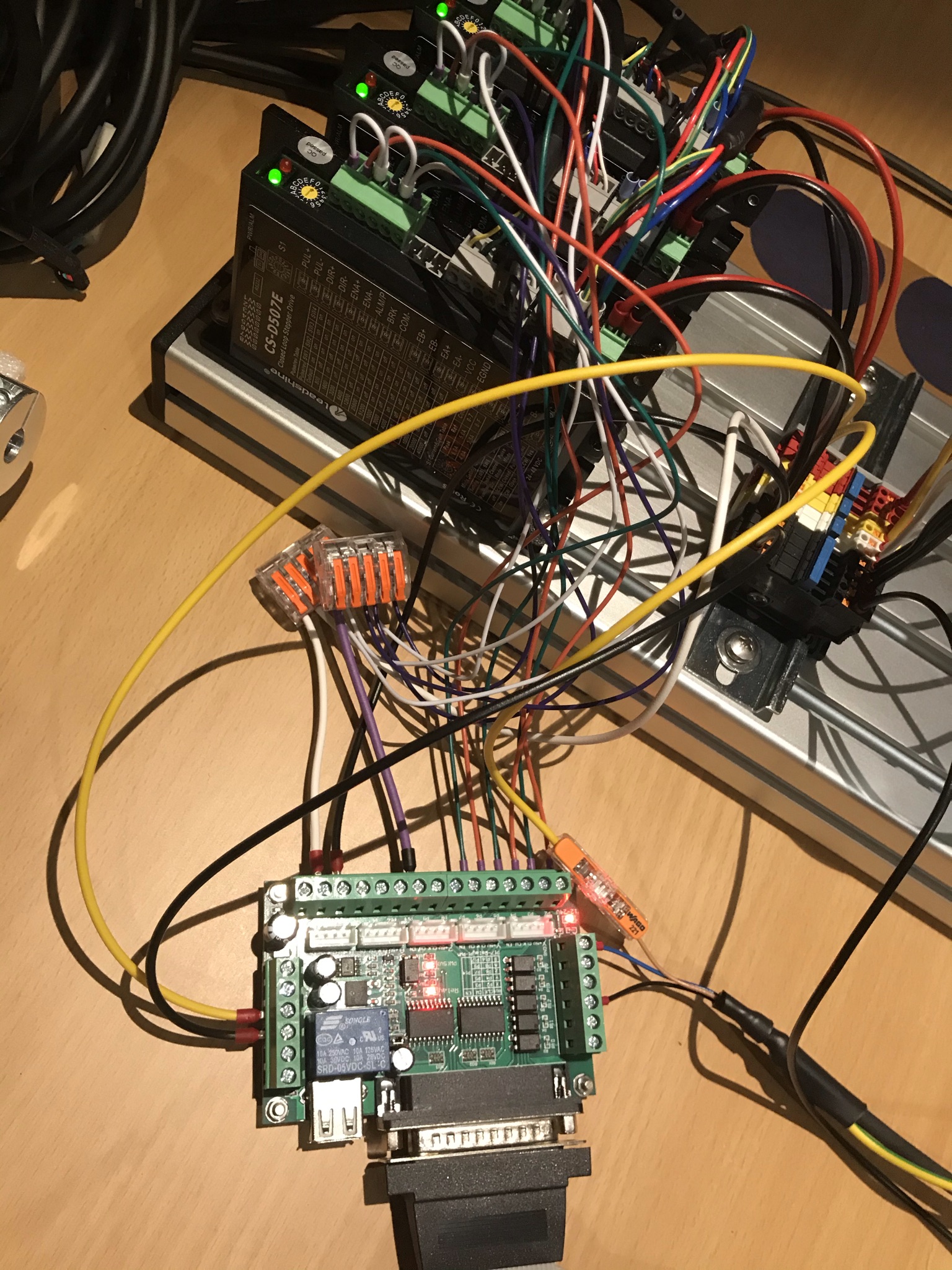
I attached some images, just to show my test setup. The colors of the wires correspond to:
Black: GND
White: 5V
Yellow: 24V
Red: 48V
Orange: PUL-
Green: DIR-
Purple: ENA-
This is 5V, and activating the limit switch does not change this voltage. The limit switch is connected to pin 12 of the BOB.
With the BOB completely disconnected from the Mesa card I still measure this 5V between HDR26 pin 10 and pin 23.
The BOB is supplied with 5V.
I attached some images, just to show my test setup. The colors of the wires correspond to:
Black: GND
White: 5V
Yellow: 24V
Red: 48V
Orange: PUL-
Green: DIR-
Purple: ENA-
Attachments:
Please Log in or Create an account to join the conversation.

13 Jul 2023 23:10 #275380
by PCW
Replied by PCW on topic BOB wiring
Something with the switch wiring?
The BOB input circuitry is really simple:
+12/24V to all OPTO LED Anodes
OPTO LED Cathodes --> 1K resistor --> terminal block Input pins
All OPTO transistor emitters grounded
OPTO transistor collectors to DB25 pins 10,11,12,13,15
(so they depend on external pullups which should be OK since the
7C81 has 3.3K pullips on all I/O pins)
Please Log in or Create an account to join the conversation.
14 Jul 2023 08:48 #275402
by Stef
Replied by Stef on topic BOB wiring
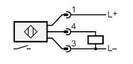
I am using a PNP normally open limit switch. The voltage between sensor pins 3 and 4 (measured on the BOB screw terminals) is 9.4V when the sensor is not activated, and 23.4V when the sensor is activated.
Sensor pin 1 is wired to the +24V from the power supply.
Sensor pin 3 is wired to GND of the BOB (so it is directly connected to the GND that is used for the 5V Mesa power supply, the 5V / 24V BOB power supplies and the 48V stepper motor power supply).
Sensor pin 4 is wired to BOB pin 12.
Sensor pin 1 is wired to the +24V from the power supply.
Sensor pin 3 is wired to GND of the BOB (so it is directly connected to the GND that is used for the 5V Mesa power supply, the 5V / 24V BOB power supplies and the 48V stepper motor power supply).
Sensor pin 4 is wired to BOB pin 12.
Attachments:
Please Log in or Create an account to join the conversation.
14 Jul 2023 14:58 #275419
by PCW
Replied by PCW on topic BOB wiring
The BOB inputs expect a connection to ground to operate
(so a NPN sensor)
(so a NPN sensor)
Please Log in or Create an account to join the conversation.
14 Jul 2023 19:02 #275430
by Stef
Replied by Stef on topic BOB wiring
Aha I see, yes then that will be the mistake, thank you for the help!
Most CNC/automation webshops in my area have much more choice in PNP sensors than NPN, so I thought PNP was more standard.
I am wondering whether I need a normally open or normally closed switch (there is no manual available for the BOB).
Most CNC/automation webshops in my area have much more choice in PNP sensors than NPN, so I thought PNP was more standard.
I am wondering whether I need a normally open or normally closed switch (there is no manual available for the BOB).
Please Log in or Create an account to join the conversation.
- OttoOrange
- Offline
- New Member
-

Less
More
- Posts: 1
- Thank you received: 0
25 Jan 2024 01:15 #291565
by OttoOrange
Replied by OttoOrange on topic BOB wiring
Another Newbie here.
I have the same BOB and you’re right … documentation doesn’t exist. My question is whether you know what the white 4 pin male connectors grouped above the X Y Z A and B connections might be for. The pins on my BOB are labelled as +5v CLK CW and NE which I believe is a typo for EN.
My stepper drivers are DRV8835 and do not seem to need to be configured for + or - step or dir. The common cathode or anode configuration?
My BOB is a DAOKI DC 12-24v CNC BOB 5 axis Mach 3. Optoisolators on the 5 input pins so I guess I need to provide at least 12v to get them to work.
Thanks
OO
Please Log in or Create an account to join the conversation.
Time to create page: 0.136 seconds