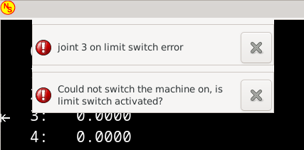
7i92 homing 'joint 3 on limit switch error'.

19 Feb 2024 20:04 #293783
by hpeyerl
7i92 homing 'joint 3 on limit switch error'. was created by hpeyerl
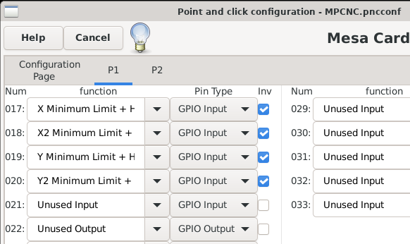
I wired up my limit switches to IO17-IO20 on P1, set them to Xmin, X2min, Ymin, Y2Min, and Inverted (because I have them wired through switches to some GND pins on P1).
When I go into HAL Show, I can switch them from Yellow to Red by manually pressing the switches. If I manually home the axis then they similarly go Red. Also checked in Hal Meter. Electrically everything seems fine.
My machine is an XXYYZ gantry. So the error seems to be pointing at the Y2 switch but this switch operates fine.
If I manually close the Y2 switch, I still get a 'Joint 3 on limit switch error'.
Strangely, One of my forays into PNCConf and not changing anything, when I came out and retried it, I got a 'Joint 1 on limit switch error' but there was no physical change to the switches or wiring.
Then it went back to Joint 3.
I'm now just confused. Thoughts?
Here's some screenshots and my .hal/.ini files.
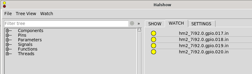
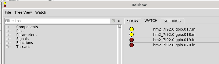
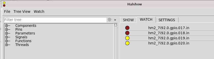
Please Log in or Create an account to join the conversation.

19 Feb 2024 20:13 #293785
by PCW
Replied by PCW on topic 7i92 homing 'joint 3 on limit switch error'.
If you are using 7I92 pins directly for limit switch inputs,
you will likely need to debounce them
you will likely need to debounce them
Please Log in or Create an account to join the conversation.
21 Feb 2024 17:55 #293916
by hpeyerl
Replied by hpeyerl on topic 7i92 homing 'joint 3 on limit switch error'.
ok. I assumed you were doing it in the FPGA but that's fine.
I re-terminated all of my connections but the problem is persistent on two of my joints. (1 and 3). To spare you the myriad debugging details, it seems to randomly be either joint 1 or 3. The problem seems to follow the cabling out to the limit switch. If I manually trigger the limit switch (by hand), a little arrow appears on the axis display of the main screen. The error appears when there are no arrows active on the screen when all the joints are in the middle of their travel and aren't moving. Sometimes it takes one or two seconds for the error to appear during which the gmoccapy 'power' icon is green.
Is it simply that those pins coming back to P1:10 (GND) are hovering too close to gnd? I can wire them to P1:18 but I don't know how to set that pin to 5V (the manual says "GND or 5V") . Is that what W3 is for? (I tried moving W3 up and now none of my limit switches will trigger but maybe I have to do something in my .hal file now?)
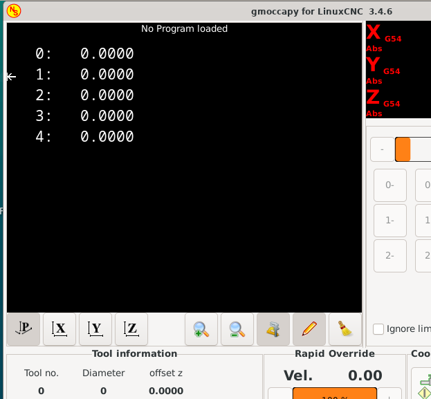
Attachments:
Please Log in or Create an account to join the conversation.
21 Feb 2024 18:09 - 21 Feb 2024 19:16 #293918
by PCW
Replied by PCW on topic 7i92 homing 'joint 3 on limit switch error'.
If W3 is "up" 5V power is supplied to P1 (HDR26 pins 18,20,22,24,26)
This is in the 7I92/7I92T manual
Using bare FPGA pins means that very short impulse noise (which is created by
axis drives and VFDs) will be seen as occasional flipped input states. You either need to
shield your limit switch wiring better, better ground your machine frame, or add filtering
to the inputs. The debounce component in LinuxCNC is typically used for this filtering
function.
There are also ways to debounce in the FPGA hardware (the inm module does this)
Last edit: 21 Feb 2024 19:16 by PCW.
Please Log in or Create an account to join the conversation.
Time to create page: 0.156 seconds