Can this be done, probing to DXF/STL?

13 Jun 2017 10:55 #94443
by tecno
Look from 2:16 Perimeter tracing and save data to file as DXF ( and/or CSV ).
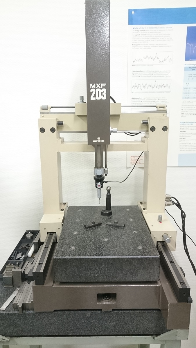
I have a small manual Mitutoyo coordinate measuring machine that I would like to get automated.
Goal is to have full 3D perimeter probing to file with preferably STL format. 2D to DXF will help a lot.
Have need to probe parts that no longer are available as spare parts.
I have Probe-It plugin in for Mach but would like to move all my machines to LCNC.
Cheers
Bengt
Can this be done, probing to DXF/STL? was created by tecno
Look from 2:16 Perimeter tracing and save data to file as DXF ( and/or CSV ).
I have a small manual Mitutoyo coordinate measuring machine that I would like to get automated.
Goal is to have full 3D perimeter probing to file with preferably STL format. 2D to DXF will help a lot.
Have need to probe parts that no longer are available as spare parts.
I have Probe-It plugin in for Mach but would like to move all my machines to LCNC.
Cheers
Bengt
Please Log in or Create an account to join the conversation.
13 Jun 2017 17:08 #94453
by newbynobi
Replied by newbynobi on topic Can this be done, probing to DXF/STL?
Hallo Benqt,
I am pretty sure, that it can be done. There is already a feature for probing, that will send the point coordinates to a file.
Your question will need a lot more maths, as the tool in the video does probe in different directions, etc.
I am very interested in your way to solve this issue, as I do have also a MITUTOYO machine I want to retrofit, I was thinking of using Acurite QC 5000 Software (now it is Heidenhain), as that one has all the maths included. As I am a metroligy Engeneer, I have the advantage to use several machines from my company, so I have this on the very last point on my todo list.
Norbert
Please Log in or Create an account to join the conversation.
13 Jun 2017 17:20 #94454
by tecno
Replied by tecno on topic Can this be done, probing to DXF/STL?
Hallo Norbert,
First of all I will keep original electronics as is, only picking up the signal from the glass scales amplifier and do some sinus to quadrature conversion and feed my controller Gecko 320X and Mach3 with Probe-It plugin but I would like to go all in with LinuxCNC.
So is there any software that reads point cloud files without any problems and spits out STL?
Bengt
Please Log in or Create an account to join the conversation.

14 Jun 2017 00:20 - 14 Jun 2017 00:24 #94495
by TurBoss
Replied by TurBoss on topic Can this be done, probing to DXF/STL?
I want to do the same but with a laser and a webcam, I would need to write a python component and there are libs out there to write stl and dxf
but sadly i don't goin to start this project soon
so if you have the signal of the probe wired to linuxcnc a python component could read the position of the machine and add a vertex or point to a dxf/stl
for future reference i found this :
- STL
w.wol.ph/2015/01/28/readingwriting-3d-stl-files-numpy-stl/
- DXF
paulcrickard.wordpress.com/2012/10/29/sh...python-to-write-dxf/
Last edit: 14 Jun 2017 00:24 by TurBoss.
Please Log in or Create an account to join the conversation.
14 Jun 2017 20:20 #94514
by jtc
Replied by jtc on topic Can this be done, probing to DXF/STL?
About one year ago I made a small python program that converts a linuxcnc probe log file in a DXF file. On this file the probing points are represented by a circle (but can be easy changed to draw lines between the log points).
I used this on a plasma cutter, where I "probe" with a laser the sample shape , or a metal sheet with hand made drawings.
there is the unfinished project:
jtctech.pt/download/jtc_dxf_writer.rar
regarding the probing, the direction can me discovered by the 2 last probe points, If you probe the next point perpendicular to that direction I think that will result like on the video.
João
Please Log in or Create an account to join the conversation.

16 Jun 2017 12:35 #94569
by andypugh
Replied by andypugh on topic Can this be done, probing to DXF/STL?
I think that the implementation of this would depend on the type of probe being used. Strain gauge probes can give extra information about the direction of touch, and I think this is what the
part-tracing CMMs
use, rather than a simple touch-probe.
Part tracing with a touch-probe has to guess what angle the probe is touching the part at.
I imagine that you would simply assume that the current point is an extension of the line through the last two points during the scanning process, (to calculate the next probe-start position) then calculate a better guess a the real tangent once all the points are gathered.
Psudo-code:
Pick a path direction, let's assume anticlockwise.
Probe from start point in the direction suggested by the operator.
return to start point
[1]probe at high speed in the direction of the last segment anticipating a no-touch.
If that move ends with a touch, back off along the previous path, turn the probing direction 10(?) degrees clockwise, try again.
if that move ends in no-touch, probe towards a line 10 degrees anticlockwise of the last segment
if that hits, retract a little and loop back to [1]
if that does not hit, retract to a point on the last segment, rotate the path 10 degrees, repeat...
You need to consider the situation where the probe might get stuck in a probe-sized hole. So I think that every move needs to be a probe move.
G-code can log data to file, so the whole thing can be a standalone G-code program.
linuxcnc.org/docs/2.7/html/gcode/overview.html#_probe_logging
Probe-logging (15) will probably put excess data in the file, so normal logging (16) of only the moves that expect to find a part would be better.
Please Log in or Create an account to join the conversation.
16 Jun 2017 12:59 #94571
by tecno
Replied by tecno on topic Can this be done, probing to DXF/STL?
Thanks Andy,
I am aware of the shortcomings with linear probing but it would be better than nothing.
Probe heads I have are TP6 and TP2 5W for this machine.
The pseudo code explains the operation very well.
Cheers
Bengt
I am aware of the shortcomings with linear probing but it would be better than nothing.
Probe heads I have are TP6 and TP2 5W for this machine.
The pseudo code explains the operation very well.
Cheers
Bengt
Please Log in or Create an account to join the conversation.
- eneias_eringer
- Offline
- Junior Member
-

Less
More
- Posts: 38
- Thank you received: 7
20 Jun 2017 14:30 #94726
by eneias_eringer
Replied by eneias_eringer on topic Can this be done, probing to DXF/STL?
I used the OMV power inspect to generate the probing like a cnc program, i did the post processor to LCNC...
May be an solution !!
May be an solution !!
The following user(s) said Thank You: jtc
Please Log in or Create an account to join the conversation.
20 Jun 2017 15:04 #94727
by tecno
Replied by tecno on topic Can this be done, probing to DXF/STL?
I assume this is a high dollar software = then it is out of my budget.
Cheers
Bengt
Cheers
Bengt
Please Log in or Create an account to join the conversation.
Time to create page: 0.264 seconds