Trajectory Planner using Ruckig Lib

")
Please Log in or Create an account to join the conversation.
- Ritterchen
- Offline
- Junior Member
-

- Posts: 20
- Thank you received: 7
I was just curious if the development of this is going on and if there is any way to support it outside of being able to contribute to the code?
I am more of an end user, but due my machines are limited from not having S-Curve Accelerations I would really love to implement and test it. Running at 1700mm/s^2 currently, but I am sure I could easly ramp it up to two-four times that and getting cutting performances close to a Datron Neo. S-Curves seems to be litlerally THE difference between any low-end and DIY machine nowadays and the industry standard controls.
Would be happy to arrange some funding etc. for this feature, I am sure many out there are with more rigid mineral casting machines or retrofits are keen to get their hands on it!
Greetings Fritz
Please Log in or Create an account to join the conversation.
- smc.collins
- Offline
- Platinum Member
-

- Posts: 655
- Thank you received: 110
Please Log in or Create an account to join the conversation.
Probably many are willing to help/contribute, just let everyone one know what you guys need to push this forward.
Please Log in or Create an account to join the conversation.
- ihavenofish
- Offline
- Platinum Member
-
- Posts: 590
- Thank you received: 84
Please Log in or Create an account to join the conversation.

The project so far worked more or less okey when each g0,g1,g2,g3 had a start and stop.
I have seen a tiny bug wich is related to loading a arc, it doesn't read if arc is clockwise or counterclockwise.
This issue is resolvable.
So far my blending tryouts failed.
Last week i started thinking about how to go on with this project.
I made a test, wich i found out to be interesting. I will tell you how it works, and i hope you will understand,
and share a conclusion about it.
The question is : Is the X-axis capable to follow the Y-axis on the path?
The path test :
We have a path, containing 3 segments :
- segment 1: a line from {0,0} to {0,80}.
- segment 2: a clockwise arc from {0,80} to {20,100}.
- segment 1: a line from {20,100} to {100,100}.
Compare the ruckig runners to a motor for x and y, using a scurve motion profile.
- ruckig scurve runner, x axis.
- ruckig scurve runner, y axis.
- perform a motion for y axis from {0,0} to {0,100}.
- when y axis is at {0,80,0} start x axis from {0,0} to {100,0}.
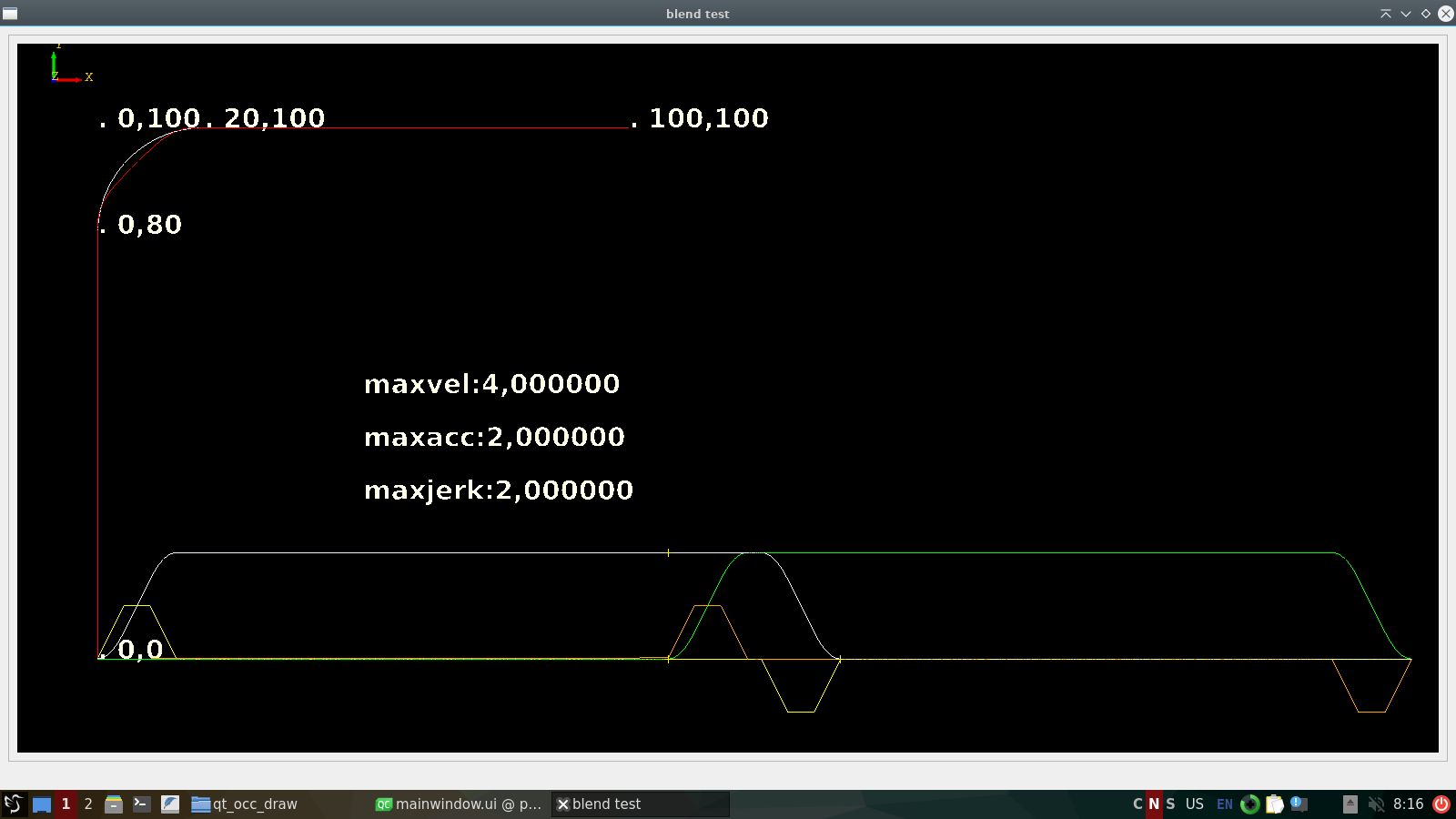
Graph map :
- On the bottom we have the velocity and acceleration graph.
- On the bottom the 2 yellow points are at {0,80}, this is the begin of the arc.
- The red line is are the position points for the ruckig runners x and y.
- The white arc in the upper left corner represents segment 2.
velocity=4.
We see the red arc in the upper left corner is inside the arc of segment 2.
This is good news. We could follow the white arc exactly doing interpolation, this involves slowing down the x axis
to follow the arc exactly.
In my opinion, this solution results in the optimal corner velocity.
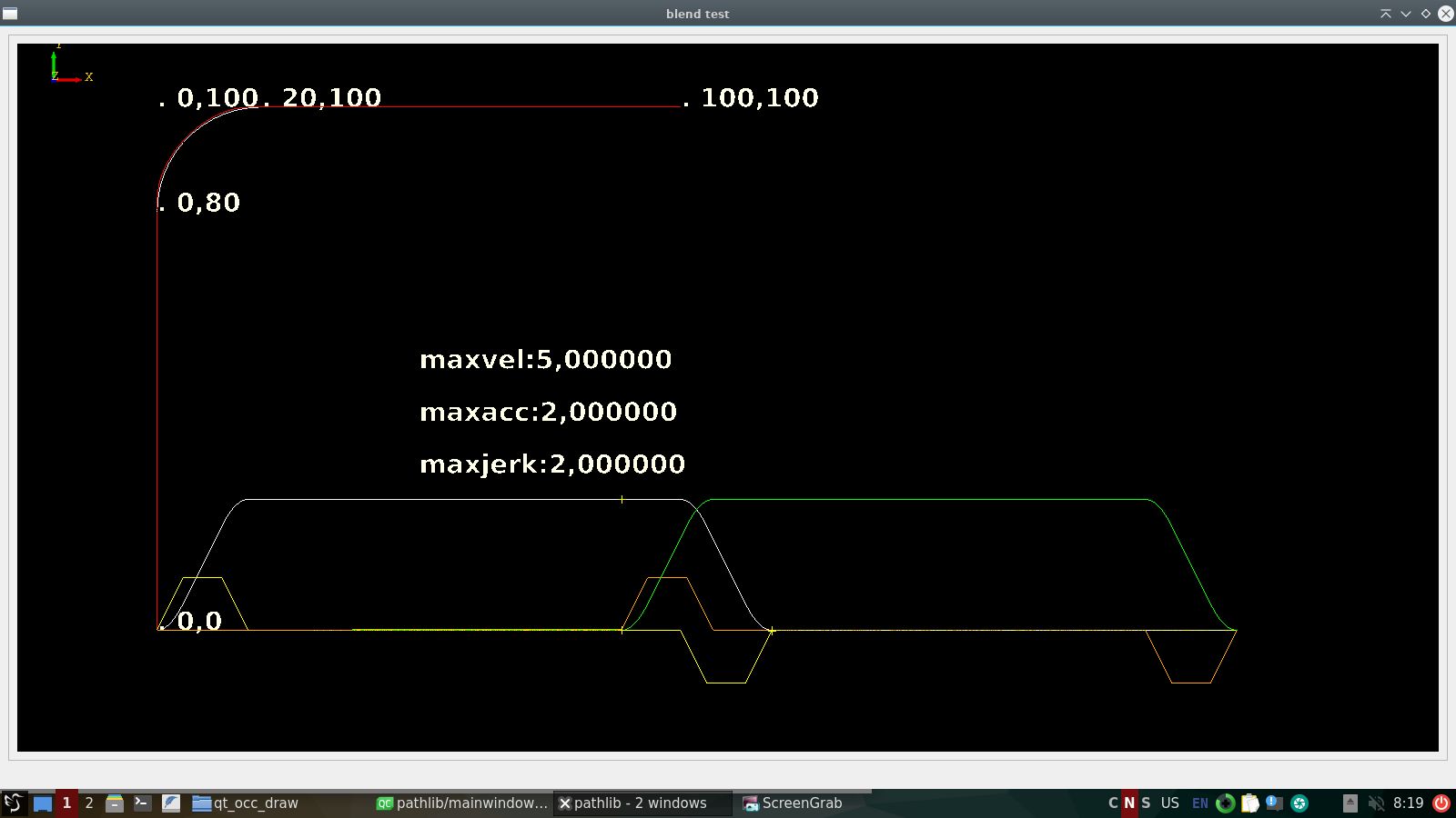
velocity=5.
It's hard to see, but the red arc is outside the white arc, interpolation to get the x axis on the arc would only
work if we increase the x axis max-acceleration value. This option fails.
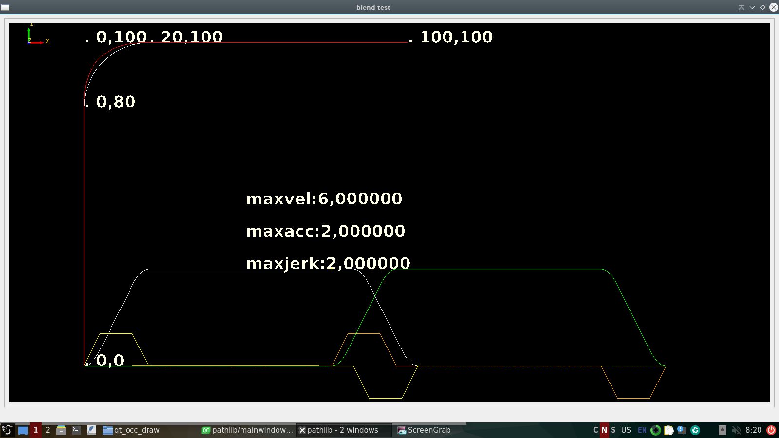
velocity=6.
The red arc is far outside the white arc. Its impossible to resolve a valid path.
I hope you can understand this mathematical problem, and i hope we can create a algoritme to solve this soon.
Please Log in or Create an account to join the conversation.
velocity=5.
It's hard to see, but the red arc is outside the white arc, interpolation to get the x axis on the arc would only
work if we increase the x axis max-acceleration value. This option fails.
I assume you get it to follow the path by increasing the max-acc? But I dont understand what you mean with ”this option fails”.
Please Log in or Create an account to join the conversation.
Yes.
I dont understand what you mean with ”this option fails”.
It's not a good thing to use value's that are above machine limits and or user input for maxacc etc.
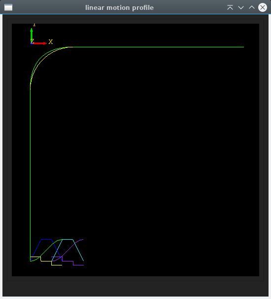
I did a second test using linear velocity profile, the 2 line and arc coordinates are the same as in previous post.
I had to make a c++ class for this, was a lot of work.
So far the waypoints that constructed the green arc, are outside the yelllow arc. The yellow arc is the exact path to follow.
So next thing is try to get exact path waypoints. With ruckig, this was a no go.
- Curve input -
vo:0.000 vm:10.000 ve:0.000 s:100.000 a:2.000
- Curve period t1 :acc
- Curve period t2 :steady
- Curve period t3 :dcc
- Curve times :
t1:5.000
t2:5.000
t3:5.000
ttot:15.000
- Curve displacement :
s1:25.000
s2:50.000
s3:25.000
stot:100.000
Attachments:
Please Log in or Create an account to join the conversation.
Today i made a code that calculates arc speeds from 3 given values, 3 constants.
1. linear max velocity. (machine maxvel), this is used to limit arc speeds to vm.
2. optimal arc speed (the perfect arc speed for your machine at the radius given by 3.)
3. the arc radius at optimal arc speed
It then calculates the angular speed in rad/sec, called Omega.
ω = linear speed / radius [rad/sec]
This omega is then a constant and is used to calculate other arc's and circle speeds at different radius.
Let's consider a example with arcs of radius 10 mm and 1000 mm, both with an angular speed of 20 rad/s,
the 20 rad/s is a constant and calculated from inputs 2,3.
- For the arc with a radius of 10 mm: vsmall arc=20 rad/s*10 mm=200 mm/s
- For the arc with a radius of 1000 mm: vlarge arc=20 rad/s*1000 mm=20000 mm/s
So the speed differs when radius changes, this is good.
Tested the code :
Input:
double radius4 = 0.01; // Radius in mm, blending G64P0.01 in LinuxCNC
double linearSpeed4 = am->calculateLinearArcSpeed(radius4);
double radius5 = 0.1; // Radius in mm, blending G64P0.1 in LinuxCNC
double linearSpeed5 = am->calculateLinearArcSpeed(radius5);
Output:
Linear Speed on the Arc with Radius :0.01 v:2.8 mm/min
Linear Speed on the Arc with Radius :0.1 v:28 mm/min
github.com/grotius-cnc/angular_motion
Please Log in or Create an account to join the conversation.
Uh..... no.So far the waypoints that constructed the green arc, are outside the yelllow arc. The yellow arc is the exact path to follow.
So next thing is try to get exact path waypoints. With ruckig, this was a no go.
I'm no porgramming expert, but I have worked in CAD/CAM as a professional, and also have a mill I use LincuxCNC on. So I realy appreciate your work here.
The point here is that when you go from straight corners with full stop with blending you alter the actual path.... we all get that. You will have corner rounding.
But.... the same happens here! When we go from simple corner rouunding to jerk limited corners the transition between the curves will "distort", and the path will obviously also look different. Just as above.
The corners will in fact end up with what is called a G2 curve. Look it up.
In your screenshot your green curve is in fact a G2 curve, where the transitions between the straitght parts and the curve have a transition, or a derivative which is the matematical description.
And.... this is a BETTER curve. If you look at it it is better resembling the sharp corner we came from. The closest part to the corner is closer to the corner with the green curce that it is for the yellow curve.
So, to me it looks like the Rucking Lib is doing it's job and modifying the curve to the desired G2 curve. This is what this lib. is doing! And you expected it to stay like the yellow corve, which is what it looks like without jerk limitation. You can't expect the curve to stay the same when you change the accelerations on the different axis indipendently. How much you allow them to change is one thing. But this is set by your allowed max accel values, and not much else.
Remember, your car will drive in a different path if you limit how fast you turn the steering wheel when turning. And you might end up having to have a sharper turn radius at the maximum if you have a low rate of turning the wheels, like your green curve. So you will have to factor this in when you set up the system. Because this might alter the requred max accelereations. But the jerks will be limited, which is the goal.
So I'd say you are absolutely going it the correct direction here!
Keep going with what you have here.
Please Log in or Create an account to join the conversation.