THCAD-10 + hypertherm 45 (nonXP)
- robertspark
- Offline
- Platinum Member
-

Less
More
- Posts: 915
- Thank you received: 216
31 Aug 2017 21:13 #98312
by robertspark
THCAD-10 + hypertherm 45 (nonXP) was created by robertspark
Hello, this seems as good a place as any to ask this one regarding the THCAD-10 interface board with a hardware / voltage divider question.
The Hypertherm 45 (nonXP) has a 50:1 voltage divider output as standard, although if you look at the Service Manual Schematics at the back of the manual, the voltage divider output appears to be 51:1 to me (won't be the first / last time I get something wrong so I may be wrong here).
The voltage divider is a 100K resistor, and a second 2K resistor listed on the schematic with the divided voltage then directly routed to the CPC [14 pin circular plastic connector?? TYCO) machine interface output.
The Operator Manual lists the open circuit voltage as potentially 7 volts at the CPC (although the Rated Open Circuit Voltage (RAW) in the operator manual is 275 VDC on a single phase supply)
I've been told that the THCAD-10 was designed for 20:1 voltage divided output, although this just does not ring true as all of the other machine interface Hypertherm products do in fact have default 20:1 divided outputs, but their open circuit voltage is potentially 18 Volts under open circuit conditions as listed in the manuals and the THCAD is 0-10V unipolar.
So, short question, what are others doing?
Are you running a 20:1 voltage divider output, if so, why? (given the normal working range of the plasma cutter voltage is about 75 - 145V, at 20:1 this would give you 3.75 to 7.25V, but anything above 200V would be clipped?
Given the PMX 45 has a 50:1 output, and the brunt of the current (and therefore power dissipation) is taken by the provided 100K resistor, is my math right to swap out the 2K resistor, and install a 3K3 resistor in series with the 2K resistor and I should get ~ 20:1 (not quite as the resistors I have to hand are 5% tolerance), but I will do my "tuning" on the software side with a calibrated input, given I'm going to struggle to calibrate the output unless I went with say a 200V zener and rectified mains to DC, filtered it, and added zener for calibration although they also have an inherant tollerance (+/- 5%) 1N5388B, where as I would use a 3K9 resistor and a 2K multi-turn pot to tune the output to 20:1..... but I don't think I'll get better than +/- 5% as I don't have a calibrated instruments
Thanks for your time and guidance
Rob
Please Log in or Create an account to join the conversation.
- rodw
-

- Offline
- Platinum Member
-
Less
More
- Posts: 11953
- Thank you received: 4070
01 Sep 2017 04:54 #98321
by rodw
Replied by rodw on topic THCAD-10 + hypertherm 45 (nonXP)
Rob, the THCAD-10 can be scaled with an external resistor on the input side very simply. The instructions for calculating the resistor value are in the THCAD manual. Whilst the example is for 500 volts, it works equally as well scaling to a 20 or 25 volt range. I scaled mine on the assumption that I had a 16:1 resistor to a 20 volt scale by adding said resistor inside the plasma interconnect cable backshell.It ended up being 25:1 so my scaling resistor needs revisiting. A 1/2 W resistor is all you need.
I think I saw that the 50:1 Hypertherm at full scale was 7 volts. Even at this level, the THCAD-10's 10V native scale will still perform well based on my experience with an incorrect scale. While cutting on my machine, the cut volts is scaled to about 2 volts out of 10 volts and its still quite accurate.
I think I saw that the 50:1 Hypertherm at full scale was 7 volts. Even at this level, the THCAD-10's 10V native scale will still perform well based on my experience with an incorrect scale. While cutting on my machine, the cut volts is scaled to about 2 volts out of 10 volts and its still quite accurate.
The following user(s) said Thank You: robertspark
Please Log in or Create an account to join the conversation.
- cruzinone
- Offline
- Junior Member
-

Less
More
- Posts: 27
- Thank you received: 0
20 Sep 2017 02:09 #99146
by cruzinone
Replied by cruzinone on topic THCAD-10 + hypertherm 45 (nonXP)
Did you ever get this sorted out? I am trying to set up a thcad card. I have a older 45 machine and want to hook up the card but do not know where to hook this in. Did you have to drill a hole in the case and if so what did you hook to with the wires coming from the thc a-d card? I have a remote cable that plugs into the back of the unit and it has 2 pins that are for remote start I am hoping I can add a couple pins in the proper spot but I dont know and found no info on this topic. I have a schematic of my unit but need to know what pins from the card go where. thanks for any help in this topic.
Please Log in or Create an account to join the conversation.
- robertspark
- Offline
- Platinum Member
-
Less
More
- Posts: 915
- Thank you received: 216
20 Sep 2017 12:54 #99161
by robertspark
Replied by robertspark on topic THCAD-10 + hypertherm 45 (nonXP)
Short answer no, busy on various things at present + trying too head under the bonnet with glade + HAL gmoccapy.
Please Log in or Create an account to join the conversation.
- rodw
-
- Offline
- Platinum Member
-
Less
More
- Posts: 11953
- Thank you received: 4070
20 Sep 2017 20:12 - 20 Sep 2017 20:12 #99176
by rodw
I think you may need a different interconnect cable or interface card. Yours might just be for a remote start pendant, not for CNC. I don't have a Hypertherm but their local rep sent me this yesterday which might help. Pinout is on Page 5
Replied by rodw on topic THCAD-10 + hypertherm 45 (nonXP)
I have a remote cable that plugs into the back of the unit and it has 2 pins that are for remote start I am hoping I can add a couple pins in the proper spot but I don't know and found no info on this topic. .
I think you may need a different interconnect cable or interface card. Yours might just be for a remote start pendant, not for CNC. I don't have a Hypertherm but their local rep sent me this yesterday which might help. Pinout is on Page 5
Last edit: 20 Sep 2017 20:12 by rodw.
Please Log in or Create an account to join the conversation.
- robertspark
- Offline
- Platinum Member
-
Less
More
- Posts: 915
- Thank you received: 216
21 Sep 2017 10:09 #99198
by robertspark
Replied by robertspark on topic THCAD-10 + hypertherm 45 (nonXP)
Essential documents for you to have + save:
PMX45 Operator Manual:
www.hypertherm.com/Download?fileId=HYP109170&zip=False
PMX45 Service Manual:
www.hypertherm.com/Download?fileId=HYP109171&zip=False
CPC Port (as given by Rod):
www.hypertherm.com/Download?fileId=HYP103957&zip=False
PMX 45 Raw Arc Voltage Connection (if you have the THCAD-300 or require raw voltage input):
www.hypertherm.com/Download?fileId=HYP103958&zip=False
1) the pmx 45 is provided as standard with a machine interface (called a CPC - circular plastic connector? As manufacturered by Tyco , I have all the pin and part numbers which I'll post later if you want to make your own leads or add pins to the CPC)
2) the pmx45 has a 50:1 divided output (non adjustable) as standard within the CPC [most other hypertherms have 20:1 voltage divider output], this is between pins 5 (-) and 6 (+) of the CPC
There is a bit of an issue over just using the CPC input with the THCAD-10 in that it's full scale range is 10 volts, but the output of the PMX45 is 0-7 volts (50:1) so ~0-350v.
This "issue" may be a non-issue in that I would like better resolution and make better use of the THCAD-10 given the cutting range of the PMX45 is ~ 90 to 145 volts, which is only 1.8 volts to 2.9 volts ... so the range is quite narrow so what I am trying to do will be to increase the usable range so that the THCAD can make better use of it .....
But to answer your question simply, you will need to wire the THCAD-10 to pins 5 (-) and 6 (+) and it will read the cutting voltage.
If you have the THCAD-300 (or if you want to use the THCAD-10 to read the RAW volts) then you will need to follow the wiring detail within the RAW arc voltage kit and wire the THCAD up to the appropriate connection points.
Extract of the manual / screenshot attached showing the CPC wiring.
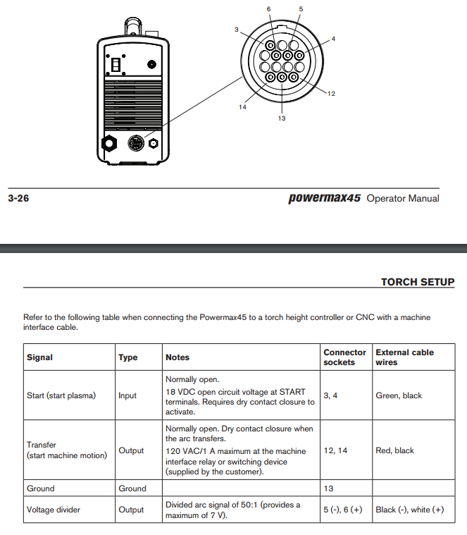
Also available in the CPC will be the torch fire (between pins 3 + 4)
and Arc Transfer (also called arcOK) signal (between pins 12 + 14)
PMX45 Operator Manual:
www.hypertherm.com/Download?fileId=HYP109170&zip=False
PMX45 Service Manual:
www.hypertherm.com/Download?fileId=HYP109171&zip=False
CPC Port (as given by Rod):
www.hypertherm.com/Download?fileId=HYP103957&zip=False
PMX 45 Raw Arc Voltage Connection (if you have the THCAD-300 or require raw voltage input):
www.hypertherm.com/Download?fileId=HYP103958&zip=False
1) the pmx 45 is provided as standard with a machine interface (called a CPC - circular plastic connector? As manufacturered by Tyco , I have all the pin and part numbers which I'll post later if you want to make your own leads or add pins to the CPC)
2) the pmx45 has a 50:1 divided output (non adjustable) as standard within the CPC [most other hypertherms have 20:1 voltage divider output], this is between pins 5 (-) and 6 (+) of the CPC
There is a bit of an issue over just using the CPC input with the THCAD-10 in that it's full scale range is 10 volts, but the output of the PMX45 is 0-7 volts (50:1) so ~0-350v.
This "issue" may be a non-issue in that I would like better resolution and make better use of the THCAD-10 given the cutting range of the PMX45 is ~ 90 to 145 volts, which is only 1.8 volts to 2.9 volts ... so the range is quite narrow so what I am trying to do will be to increase the usable range so that the THCAD can make better use of it .....
But to answer your question simply, you will need to wire the THCAD-10 to pins 5 (-) and 6 (+) and it will read the cutting voltage.
If you have the THCAD-300 (or if you want to use the THCAD-10 to read the RAW volts) then you will need to follow the wiring detail within the RAW arc voltage kit and wire the THCAD up to the appropriate connection points.
Extract of the manual / screenshot attached showing the CPC wiring.
Also available in the CPC will be the torch fire (between pins 3 + 4)
and Arc Transfer (also called arcOK) signal (between pins 12 + 14)
Please Log in or Create an account to join the conversation.
- robertspark
- Offline
- Platinum Member
-
Less
More
- Posts: 915
- Thank you received: 216
21 Sep 2017 10:43 - 21 Sep 2017 10:52 #99199
by robertspark
Replied by robertspark on topic THCAD-10 + hypertherm 45 (nonXP)
Hypertherm CPC (Circular Plastic Connector) components should you wish to make an interface cable of your own (or add additional pins to the plasma cutter CPC connector)
The connector is made by TYCO and all of the components are listed within this manual, and the part numbers are their numbers,
www.te.com/commerce/DocumentDelivery/DDE..._0807.pdf%7F206044-1
www.te.com/commerce/DocumentDelivery/DDE...038_A.pdf%7F206044-1
206044-1 Plug Shell [1 number required]
206070-8 Cable Clamp [1 number required]
164164-1 Pins (male - lead side) [ 7 number required, including ground conn. ]
66101-9 Pins (female - machine side) [only required if you want or need to install additional pins, this should not be required]
Oh, check the quantities at time of order as some of the pins are only sold as singles or packs of 4 or 5 etc
If you search on ebay (or as I did RS components as cheaper in the UK) you can find them, I suspect DigiKey or Mouser in the US will be better but we get hammered on import tax.
RS Components I believe also own CPC [preston] and also farnell in the UK hence having a search of the three for electronic components may bring up different costs + free shipping some times.
The part numbers came mainly from here (Jim Colt post):
www.cnczone.com/forums/hypertherm-plasma...rum.html#post1146019
One of the cleverest things I've seen done is this:
i.ebayimg.com/00/s/MTAzNlgxNjAw/z/yBUAAOSwBLlU56lt/$_1.JPG
this is sold as part of the miniTHC hypertherm kit. minithc.com/
It is clever because once you have an RJ45 connector, extending the lead in the future or using screened + shielded twisted pair may provide better noise immunity especially if you are sampling very small voltages our of the PMX45 with it's 50:1 divided output then noise may affect the signal especially if using unsheilded cable. hence CAT 6E screened + sheulded twised pair ethernet cable can be a good + cheap choice and it's available as an external grade hence will be more abrasion tolerant in a workshop enviroment.
Last edit: 21 Sep 2017 10:52 by robertspark.
The following user(s) said Thank You: rodw
Please Log in or Create an account to join the conversation.
- robertspark
- Offline
- Platinum Member
-
Less
More
- Posts: 915
- Thank you received: 216
23 Sep 2017 08:21 #99309
by robertspark
Replied by robertspark on topic THCAD-10 + hypertherm 45 (nonXP)
It seems I had been a bit of a Muppet.... Too many projects + work distraction...
I was considering changing the 2k resistor within the pmx45 to change the divided output from 1:50 to 1:20 or something else (1:10 with an offset of -6v)
The problem I was having was offset....
Given the range of the thcad-10 is 10 volts, and anything less than ~70 torch volts and anything greater than ~170 torch volts given these are outside of the cutting range ( by a fair amount ), hence any voltage above and below this should be ignored and the torch (z-axis) should not rise, fall or try to track the voltage ..... When in doubt... Stay put....
Instead of thinking of the problem as a voltage divider change, I realised that this will only change the signal gain (plus I am reluctant to put a soldering iron to a perfectly good low mileage plasma cutter)
I thought about using an opamp, to simply offset the voltage, and then amplify the signal and have come across a few cheap ad620 development boards which offer the opportunity to do just that very simply and require:
- Two ad620 boards (first provide signal offset at a gain of 1, then amplify the signal with a signal gain 2.5)
- An isolated power supply providing dual (+/0/-) 12 volts for the opamp. A dual supply is required to provide the offset stage.
... Hence that is the plan at present ... Just awaiting the slow boat from China with boards to try out.. (more time to get my head around linuxcnc under the hood)
Rob
Please Log in or Create an account to join the conversation.
- robertspark
- Offline
- Platinum Member
-
Less
More
- Posts: 915
- Thank you received: 216
23 Sep 2017 09:03 #99310
by robertspark
Replied by robertspark on topic THCAD-10 + hypertherm 45 (nonXP)
Anyone reading this thread amongst other things may be thinking, once you've distorted the perfectly good divided output voltage from the pmx45 how on earth are you going to know 90 volts within linuxcnc is actually 90v at the torch tip?
I've got good quality multimeters and a scopemeter But none have been calibrated... Hence use them for a check but would not trust their readings for 100% displaying voltage to 1 significant figure
I came across precision voltage reference chips a while ago and picked up an AD584 a while ago, and they are available as cheap PCB's and I'd suggest if you are in need of calibrating anything they are a good cheap source of a reliable accurate voltage for calibration.
www.analog.com/media/en/technical-docume...ata-sheets/AD584.pdf
www.ebay.co.uk/itm/AD584-High-Precision-...p2057872.m2749.l2649
Please Log in or Create an account to join the conversation.
- rodw
-
- Offline
- Platinum Member
-
Less
More
- Posts: 11953
- Thank you received: 4070
23 Sep 2017 10:58 #99321
by rodw
Replied by rodw on topic THCAD-10 + hypertherm 45 (nonXP)
My quick and dirty methocd was to wire 2 x 48v power supplies in series to give 96 volts and feed that through the plasma divider board and check with a multimeter. I think the output of a 50:1 divider will be enough, but you could scale it with one of these:
www.ebay.com.au/itm/LM358-Weak-Signal-Co...p2057872.m2749.l2649
I think you will need to calibrate the board in a similar way because I found the plasma voltage divider resistors were counted by the THCAD as being part of the scaling resistor so my 50:1 divider became 75:1.
www.ebay.com.au/itm/LM358-Weak-Signal-Co...p2057872.m2749.l2649
I think you will need to calibrate the board in a similar way because I found the plasma voltage divider resistors were counted by the THCAD as being part of the scaling resistor so my 50:1 divider became 75:1.
The following user(s) said Thank You: robertspark
Please Log in or Create an account to join the conversation.
Moderators: snowgoer540
Time to create page: 0.289 seconds