Hello everyone,
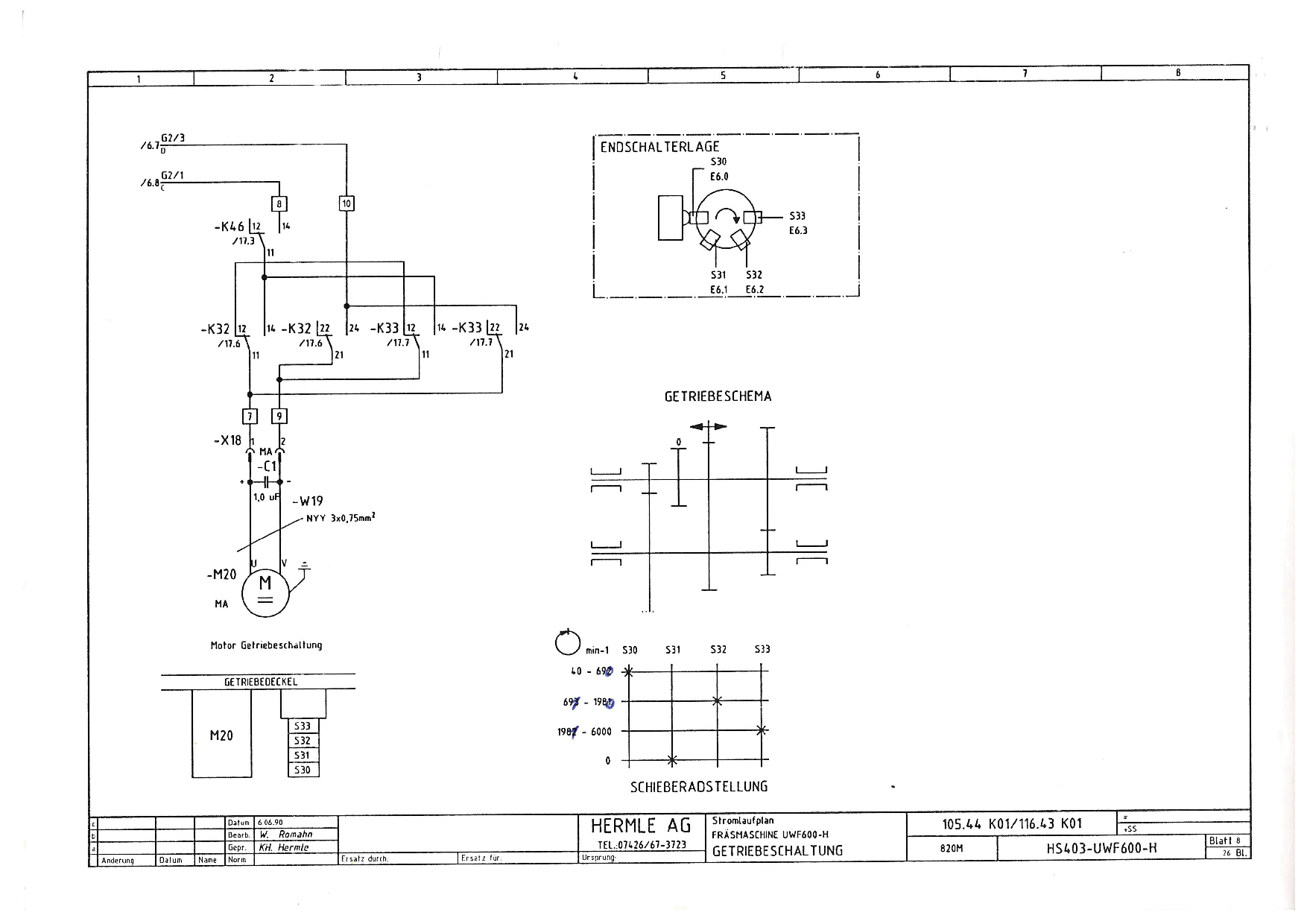
I am trying to get the gearchange on my Hermle to happen automatically.
It has 4 gear positions controlled by a 12V DC motor.
0
40-690
691-1980
1981-6000
Each position has a micro switch. To change gear the motor has turn in the appropriate direction (it can`t make a full turn). Also while changing gears, the spindle oscillates at 5Hz at a slow speed.
At first i thought about realizing the gearchange in classiclader, but in other threads it was pointed out that it can only handle integers. So the gearchange would be possible, but the scaling of the PWM signal for the spindle drive (+-10V) can´t happen there (and the result would be messy).
So I looked around and found some modified versions of gearchange.comp by andypugh. I´ve had no experience with HAL components, so I started reading about them. I understand the basic structure now and I have compiled an example component (and3.comp). But that’s it.
From what I have seen, all these components work with clutches to engage and disengage gears.
I also looked at RotarySMPs gearchange code for the Maho, but I don´t understand a thing.
My thoughts on a custom component:
-it must not do anything when the spindle is turning (spindle at speed signal or PWM output !=0)
-it needs to read the speed command and check if it’s in the right range (first if else if loop)
-if the range is correct, scale the output speed command accordingly and exit-if in the wrong range, create 5Hz signal and move DC motor in the right direction until the according switch goes on (and change PWM scale)(Second if else if loop)
-also set the PWM scaling to 0 to prevent spindle movement
But here’s a problem I can´t figure out:
I only want the gearchange if spindle speed is 0. but as soon as I try to change the gear and create the 5Hz signal, the spindle speed isn´t 0 anymore. So the gearchange would stop?!
Also it should not react to spindle speed override poti.
Do you think this is the right way to go about this?Can you think of comps that roughly fit my needs, so i can fiddle with them?
Attached is a picture of the gear schematic and motor control.