
- Posts: 43
- Thank you received: 0
eccentric turning
- Peter_Cassar
- Offline
- Senior Member
-

Less
More
7 years 11 months ago #121654
by Peter_Cassar
Replied by Peter_Cassar on topic eccentric turning
It's a German designed Optimum 2004 see ->
www.machineryhouse.com.au/L687
It's back end looks similar to the lathe in the video you linked too. Nice thing about these lathes is the tapered gibs and hardened bed for a machine made in China it has a few bells and whistles. I scrapped all the screw cutting stuff because it was a let down , no back gear or tumbler reverse. I'll open it up again and see what sort of reduction drive I can squeeze in.
It's back end looks similar to the lathe in the video you linked too. Nice thing about these lathes is the tapered gibs and hardened bed for a machine made in China it has a few bells and whistles. I scrapped all the screw cutting stuff because it was a let down , no back gear or tumbler reverse. I'll open it up again and see what sort of reduction drive I can squeeze in.
Please Log in to join the conversation.

7 years 11 months ago #121655
by andypugh
Replied by andypugh on topic eccentric turning
I have my suspicion that "German Designed" means "rip off of the Emco"
www.lathes.co.uk/emco/page2.html
www.lathes.co.uk/emco/page2.html
Please Log in to join the conversation.
- Peter_Cassar
- Offline
- Senior Member
-
Less
More
- Posts: 43
- Thank you received: 0
7 years 11 months ago #121656
by Peter_Cassar
Replied by Peter_Cassar on topic eccentric turning
You're probably right, it looks very similar. It's probably one of the better products coming out of that country in this market for the money though.
I just tried it out and successfully produced a hexagon in 5/8" brass bar. I realised that the lathe already has the reduction belt drive and bottom speed is 30rpm with useful torque . I think I might look at a larger reduction by fitting different pulleys to get down to 15rpm. 12 sided polygon yields a following error in X at 30rpm . I'd like 12 tooth cutters.
As it is I think I can produce a 6 tooth cutter with form relief , this is far better than fly cutting. I will look at a pre gashed blank to see how cutting goes but a solid blank may be OK and gash after.
This really simplifies a lot of mechanical complexity.
Please Log in to join the conversation.
7 years 10 months ago #121660
by andypugh
Replied by andypugh on topic eccentric turning
I have been enjoying this, making relieved gear hobs was on my list of things to try, you have proved the concept out,
I think that I will probably try using lincurve and cunning scaling to generate an asymmetrical form, but this is looking like it can work.
I think that I will probably try using lincurve and cunning scaling to generate an asymmetrical form, but this is looking like it can work.
Please Log in to join the conversation.
- Peter_Cassar
- Offline
- Senior Member
-
Less
More
- Posts: 43
- Thank you received: 0
7 years 10 months ago #121661
by Peter_Cassar
Replied by Peter_Cassar on topic eccentric turning
Andy, I'm going to try for a sinusoid with at least six peaks. The hobb idea is probably the better way to go for involute gears as only the single point tool is needed ground to the pressure angle. I was thinking about threading with this method to get a lobbed thread, you're thinking ahead. With clock (cycloidal) wheels , they can be hobbed but you need a different hobb for each module and tooth to pinion leaf ratio. Most of the time we are using single wheel cutters per module which is an approximation , so it will be feasible to make a form relieved single gang cutter using the eoffsets per angle as in what we're doing here.
I just found a 40:1 worm drive reduction gearbox in the workshop (2 actually and they could be coupled) , I'll next look at a way of coupling it to the lathe headstock spindle. I'll probably drive it with an auxiliary motor.
It's all very promising.
I just found a 40:1 worm drive reduction gearbox in the workshop (2 actually and they could be coupled) , I'll next look at a way of coupling it to the lathe headstock spindle. I'll probably drive it with an auxiliary motor.
It's all very promising.
Please Log in to join the conversation.
7 years 10 months ago #121662
by andypugh
Now you have made your CNC relieving lathe, making a gear hobbing machine is relatively trivial...
Replied by andypugh on topic eccentric turning
Peter_Cassar wrote: The hobb idea is probably the better way to go for involute gears as only the single point tool is needed ground to the pressure angle. I was thinking about threading with this method to get a lobbed thread, you're thinking ahead. With clock (cycloidal) wheels , they can be hobbed but you need a different hobb for each module and tooth to pinion leaf ratio. Most of the time we are using single wheel cutters per module which is an approximation.
Now you have made your CNC relieving lathe, making a gear hobbing machine is relatively trivial...
Please Log in to join the conversation.
- Peter_Cassar
- Offline
- Senior Member
-
Less
More
- Posts: 43
- Thank you received: 0
7 years 10 months ago #121664
by Peter_Cassar
Replied by Peter_Cassar on topic eccentric turning
That's on the list of things to do! That looks like a belt driven rotary axis and it works well.
Please Log in to join the conversation.
- Peter_Cassar
- Offline
- Senior Member
-
Less
More
- Posts: 43
- Thank you received: 0
7 years 10 months ago #121694
by Peter_Cassar
Replied by Peter_Cassar on topic eccentric turning
Here's a small pic of a sine wave modulation on the end of brass bar. I have added a reduction drive to the spindle to achieve sub 20RPM so that more than 12 peaks can be achieved.
Please Log in to join the conversation.

7 years 10 months ago #121695
by rodw
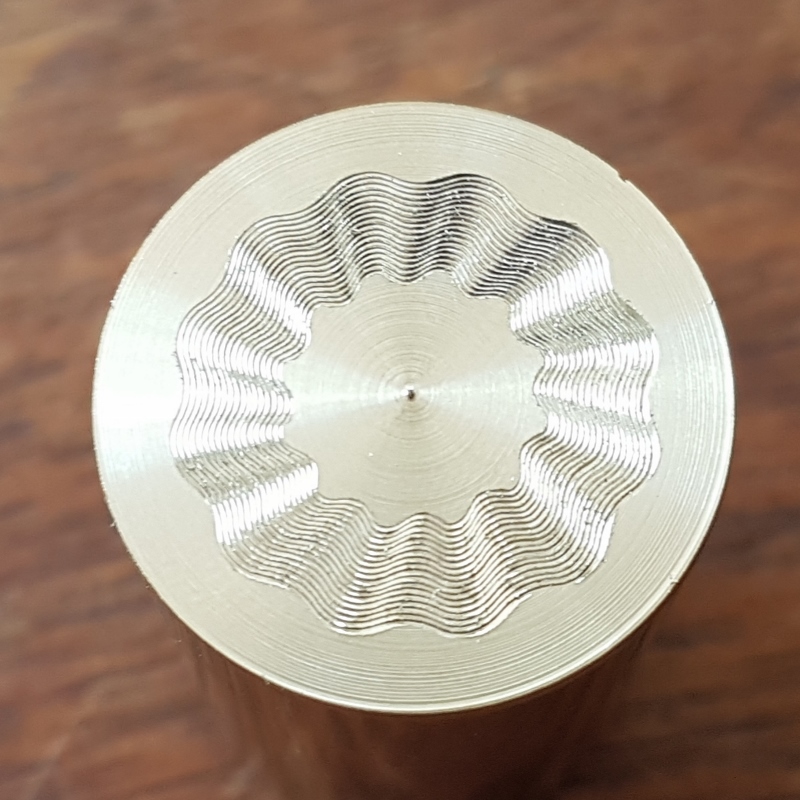
Looks awesome Peter. Great to see the external offsets in action.
It would be very cool if you wrote a component that calculated the involute gear form now.
There is some background and a link to some code on git hub here:
engineering.stackexchange.com/questions/...ute-gear-calculation
Good Luck. I'm sure Andy will help you. Sadly I don't think my maths is strong enough.
Replied by rodw on topic eccentric turning
Looks awesome Peter. Great to see the external offsets in action.
It would be very cool if you wrote a component that calculated the involute gear form now.
There is some background and a link to some code on git hub here:
engineering.stackexchange.com/questions/...ute-gear-calculation
Good Luck. I'm sure Andy will help you. Sadly I don't think my maths is strong enough.
Please Log in to join the conversation.
- Peter_Cassar
- Offline
- Senior Member
-
Less
More
- Posts: 43
- Thank you received: 0
7 years 10 months ago #121699
by Peter_Cassar
Replied by Peter_Cassar on topic eccentric turning
Rod, I was thinking that as I watched the cutting action, it's not far off how a gear could be produced.
Please Log in to join the conversation.
Time to create page: 0.124 seconds