

- Posts: 12160
- Thank you received: 0
Do you really need a spring loaded pinion drive?
10 years 1 month ago #80586
by rodw
Thanks Andy, so that's 94.25mm v's my rough measurement. I've got a 5:1 timing belt reduction set here so that will give me about 18.85mm per revolution. I'll make a reduction setup that mounts to to the NEMA 23 tapped holes so it can be swapped in and out with the direct drive as part of the learning experience.
Replied by rodw on topic Do you really need a spring loaded pinion drive?
andypugh wrote: 20 x 1.5 x pi per rev, I think.
You might as well build it and make it work anyway, seeing stuff actually move is a real encouragement.
Thanks Andy, so that's 94.25mm v's my rough measurement. I've got a 5:1 timing belt reduction set here so that will give me about 18.85mm per revolution. I'll make a reduction setup that mounts to to the NEMA 23 tapped holes so it can be swapped in and out with the direct drive as part of the learning experience.
Please Log in to join the conversation.
10 years 3 weeks ago #81412
by rodw
Replied by rodw on topic Do you really need a spring loaded pinion drive?
Life's been incredibly busy and I've had no time to get to this for weeks but have finally revisited the design to take into account for feedback on this thread. It still needs a bit of refinement. I have a 60:15 timing belt setup (eg. 3:1 reduction). That will give mea bout 31.4mm per revolution which is closer to the mark.

I kept the belt as short as I could but it proved tricky to get clearance for the belt against the mounting posts so I needed to rotate the stepper and place one post inside the belt.
I also bought a 10 tooth pulley to add to my collection. It said the maximum size hole you could use in it was 6mm and of course I had a 1/4" shaft on my stepper (6.35mm) I had hoped I could get away with the larger shaft but I don't believe I can. If I use it, I'll be down to 15.7mm per rev. I might grab another stepper motor with a 6mm shaft as it will be interesting to see the difference. I'm not sure if I'll get any time this weekend to actually work on this.
Any more feedback would be appreciated.
Please Log in to join the conversation.
- tommylight
-

- Offline
- Administrator
-

Less
More
- Posts: 22010
- Thank you received: 3
10 years 3 weeks ago #81440
by tommylight
Replied by tommylight on topic Do you really need a spring loaded pinion drive?
60:15 is 4:1
31mm per revolution is quite usable, but at low speeds (100-300mm/minute) will cause vibrations, quite noisy ones.
31mm per revolution is quite usable, but at low speeds (100-300mm/minute) will cause vibrations, quite noisy ones.
Please Log in to join the conversation.
10 years 3 weeks ago #81446
by rodw
Tommy,
Thanks. I really appreciate your guidance. I doubt I'll be cutting material thick enough to get down to those speeds. I checked again and I do have 3:1. just that its 45:15, not the 60, I stateed earlier.
I made some progress on this today but still need to make the shaft for the pinion drive.

And the other side incorporating belt adjustment slots.
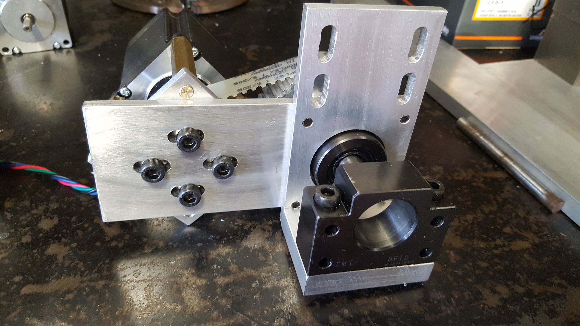
I have an issue with clearance on the stepper leg closest to the pulley (well lack of it )

I just have to decide how to fix this.
a) Turn the leg down (lazy way)
b) remake the plate the legs are mounted to and rotate it so the leg is out of the road.
c) Buy another stepper with a 6mm shaft so I can use a smaller 10 tooth pulley
Option C will give me a 4.5:1 reduction which will give 20.9mm per revolution. Lets do it right! I just ordered a stepper motor.
Replied by rodw on topic Do you really need a spring loaded pinion drive?
tommylight wrote: 60:15 is 4:1
31mm per revolution is quite usable, but at low speeds (100-300mm/minute) will cause vibrations, quite noisy ones.
Tommy,
Thanks. I really appreciate your guidance. I doubt I'll be cutting material thick enough to get down to those speeds. I checked again and I do have 3:1. just that its 45:15, not the 60, I stateed earlier.
I made some progress on this today but still need to make the shaft for the pinion drive.
And the other side incorporating belt adjustment slots.
I have an issue with clearance on the stepper leg closest to the pulley (well lack of it
)
I just have to decide how to fix this.
a) Turn the leg down (lazy way)
b) remake the plate the legs are mounted to and rotate it so the leg is out of the road.
c) Buy another stepper with a 6mm shaft so I can use a smaller 10 tooth pulley
Option C will give me a 4.5:1 reduction which will give 20.9mm per revolution. Lets do it right! I just ordered a stepper motor.
Please Log in to join the conversation.
10 years 2 weeks ago #81572
by rodw
Replied by rodw on topic Do you really need a spring loaded pinion drive?
Well, I'm slowly making progress with this. I managed to turn up the spindle for the pinion drive. If you imagine the thick part is the equivalent to the thread on a 16mm ball screw, the next 2 surfaces are the bearing journals and the pinion goes on one end and the Timing pulley on the other

NOw if only it actually all fits up! Too late tonight to try it out
I was a bit worried about this as the thread is a M12 x 1 so I had no choice but to turn it in the lathe and its only the second thread I have ever cut on my lathe
NOw if only it actually all fits up! Too late tonight to try it out
I was a bit worried about this as the thread is a M12 x 1 so I had no choice but to turn it in the lathe and its only the second thread I have ever cut on my lathe
Please Log in to join the conversation.
10 years 2 weeks ago #81640
by rodw
Replied by rodw on topic Do you really need a spring loaded pinion drive?
Well the spindle went in fine and I rotated the motor so the leg now longer fouls the pulley or belt and this is what I ended up with
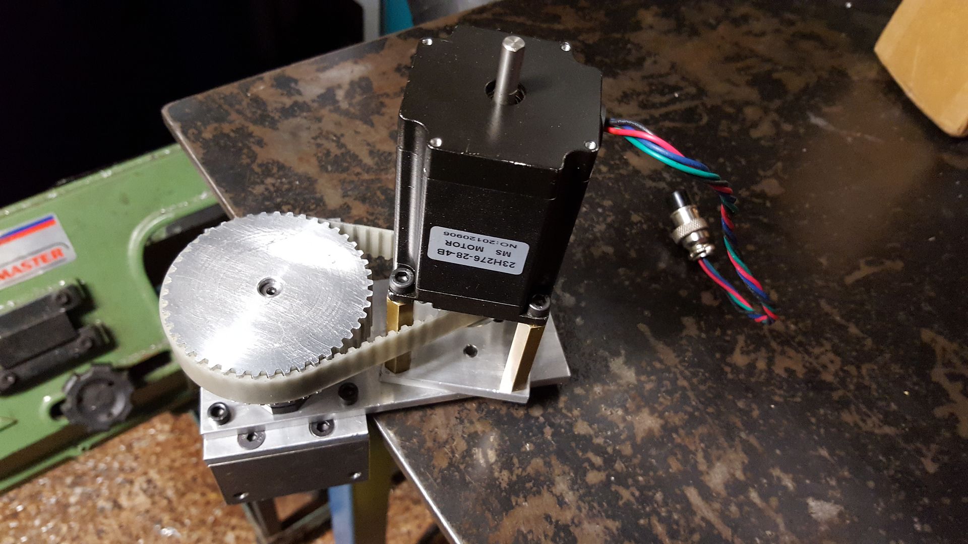
So now, All I have to do is marry this all together:


3.5 months of effort in my meagre spare time is finally coming together. Thanks for everybody's help along the journey so far. This pinion drive thread has been particularly valuable.
So now, All I have to do is marry this all together:
3.5 months of effort in my meagre spare time is finally coming together. Thanks for everybody's help along the journey so far. This pinion drive thread has been particularly valuable.
Please Log in to join the conversation.
- tommylight
-
- Offline
- Administrator
-
Less
More
- Posts: 22010
- Thank you received: 3
10 years 2 weeks ago #81663
by tommylight
Replied by tommylight on topic Do you really need a spring loaded pinion drive?
Lucky you, i get frustrated and start loosing interest after a week or two.
I have currently 4 projects on stand by because of lack of time, another 7 or 8 on the works and 1 pending.
To much projects, not enough time, it is 3:06 AM here now, got out of the workshop about half hour ago.
Your build is looking nice, and i know it takes a lot of time. Till January this year i built machines that work, look bad. Since January i am building them to look good so it is taking to much of my time, but it has to be done.
Please Log in to join the conversation.
10 years 2 weeks ago #81664
by rodw
Thanks Tommy. If the truth be known, this is the second coming. I started well over 12 months ago and put all the electronics together and could never get LinuxCNC to talk to my parallel port. It sat gathering dust bside my office desk until one day I looked at it and remembered how much time and money was tied up in this inert box so I decided to do something about it and ordered a bunch of stuff and a Mesa card from John which is still untouched.
It is rewarding to build a bunch of parts and finally be able to assemble them into something useful. I am trying to resist the temptation to move on to another part of the build (like the electronics) before the hardware I am working on is finished. Once I get these 2 axes completed I'm onto the electrinics and am hoping to con the fabricators at work build the table for me.
Im a totally self taught machinist so its slow going....
Replied by rodw on topic Do you really need a spring loaded pinion drive?
tommylight wrote: Lucky you, i get frustrated and start loosing interest after a week or two.
I have currently 4 projects on stand by because of lack of time, another 7 or 8 on the works and 1 pending.
To much projects, not enough time, it is 3:06 AM here now, got out of the workshop about half hour ago.
Your build is looking nice, and i know it takes a lot of time. Till January this year i built machines that work, look bad. Since January i am building them to look good so it is taking to much of my time, but it has to be done.
Thanks Tommy. If the truth be known, this is the second coming. I started well over 12 months ago and put all the electronics together and could never get LinuxCNC to talk to my parallel port. It sat gathering dust bside my office desk until one day I looked at it and remembered how much time and money was tied up in this inert box so I decided to do something about it and ordered a bunch of stuff and a Mesa card from John which is still untouched.
It is rewarding to build a bunch of parts and finally be able to assemble them into something useful. I am trying to resist the temptation to move on to another part of the build (like the electronics) before the hardware I am working on is finished. Once I get these 2 axes completed I'm onto the electrinics and am hoping to con the fabricators at work build the table for me.
Im a totally self taught machinist so its slow going....
Please Log in to join the conversation.
10 years 2 weeks ago #81686
by rodw
Replied by rodw on topic Do you really need a spring loaded pinion drive?
Well, I made some progress over the weekend

THe rack is not mounted yet.
I'm starting to get excited!
Just a few little tweaks and this Y axis is done.
1. I need to space up the rack by 5mm . That will let the pinion assembly clear the top Linear rail.
2. I need to make a slight tweak to the drive shaft so the pinion is properly aligned and therefore engages for the full width.
3. Remake the mounting plate which has a few extra holes in it due to an earlier stuff up. I've adjusted a couple of hole positions so hopefully, the finished product won't need to be notched to clear the pulley.
The good news was with everything in position and adjusted up, there was no sign of backlash so thanks guys for all the help.
I do have one question though. The rack is 17mm wide and has tapped mounting holes every 5.75" on the back surface. Should I space it up with a length of aluminium or could I get away with putting machined spacer washers under each mounting bolt? I guess that has the advantage of not letting crud build up on top of the rack but might not be as well supported.
Any ideas about this would be welcomed.
Please Log in to join the conversation.
10 years 1 week ago #81746
by andypugh
I think I would prefer to see it solidly supported if it was mine.
You could, however, make the spacers to get the position right, then assemble with a sausage of epoxy putty underneath to fill the gap and stop the rack bowing (and, probably more critically, ringing)
Replied by andypugh on topic Do you really need a spring loaded pinion drive?
rodw wrote: Should I space it up with a length of aluminium or could I get away with putting machined spacer washers under each mounting bolt?.
I think I would prefer to see it solidly supported if it was mine.
You could, however, make the spacers to get the position right, then assemble with a sausage of epoxy putty underneath to fill the gap and stop the rack bowing (and, probably more critically, ringing)
Please Log in to join the conversation.
Time to create page: 0.142 seconds