- Hardware & Machines
- Driver Boards
- How do you pass shielded servo motor cables through the cabinet wall/panel?
How do you pass shielded servo motor cables through the cabinet wall/panel?

Please Log in or Create an account to join the conversation.

You don't. Look at the Siemens video I linked above.So if you use a ground clamp as suggested by above links above, how do you connect the shield to the drive connector terminal block?
Note that you must still connect the ground conductor between the motor and the drive terminal, for safety.
Please Log in or Create an account to join the conversation.
A grounding cable is of course present!
Please Log in or Create an account to join the conversation.

The video shows use of a cable for servos with an additional ground conductor. In the case of a 4 wire stepper system, some quality stepper drives require the shield to be terminated at the drive as this diagram from the manual of a Lam Technologies DS1076A shows.
So if you use a ground clamp as suggested by above links above, how do you connect the shield to the drive connector terminal block?
You don't. Look at the Siemens video I linked above.
Note that you must still connect the ground conductor between the motor and the drive terminal, for safety.
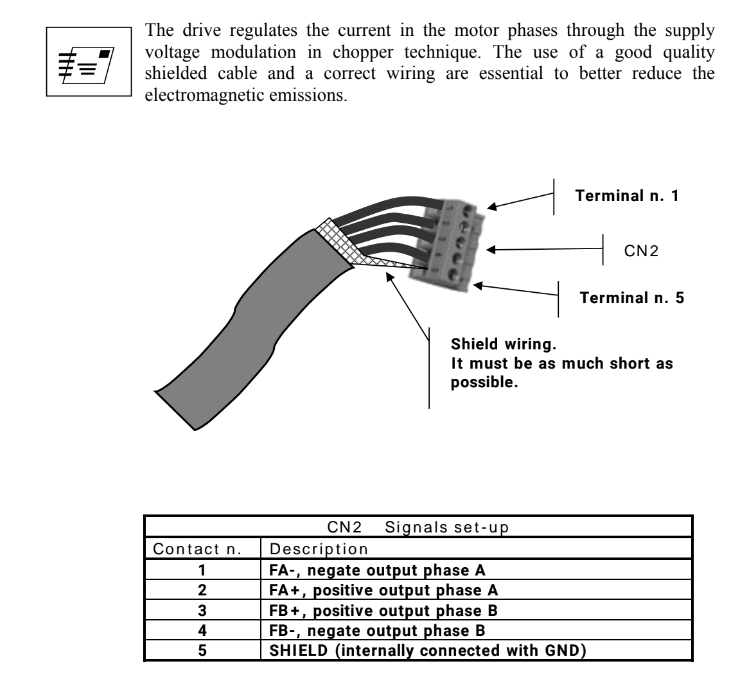
Ref: www.lamtechnologies.com/Product.aspx?lng=EN&idp=DS1076
Elsewhere, they suggest the cable pass through the cabinet intact (eg. via a cable grommet)
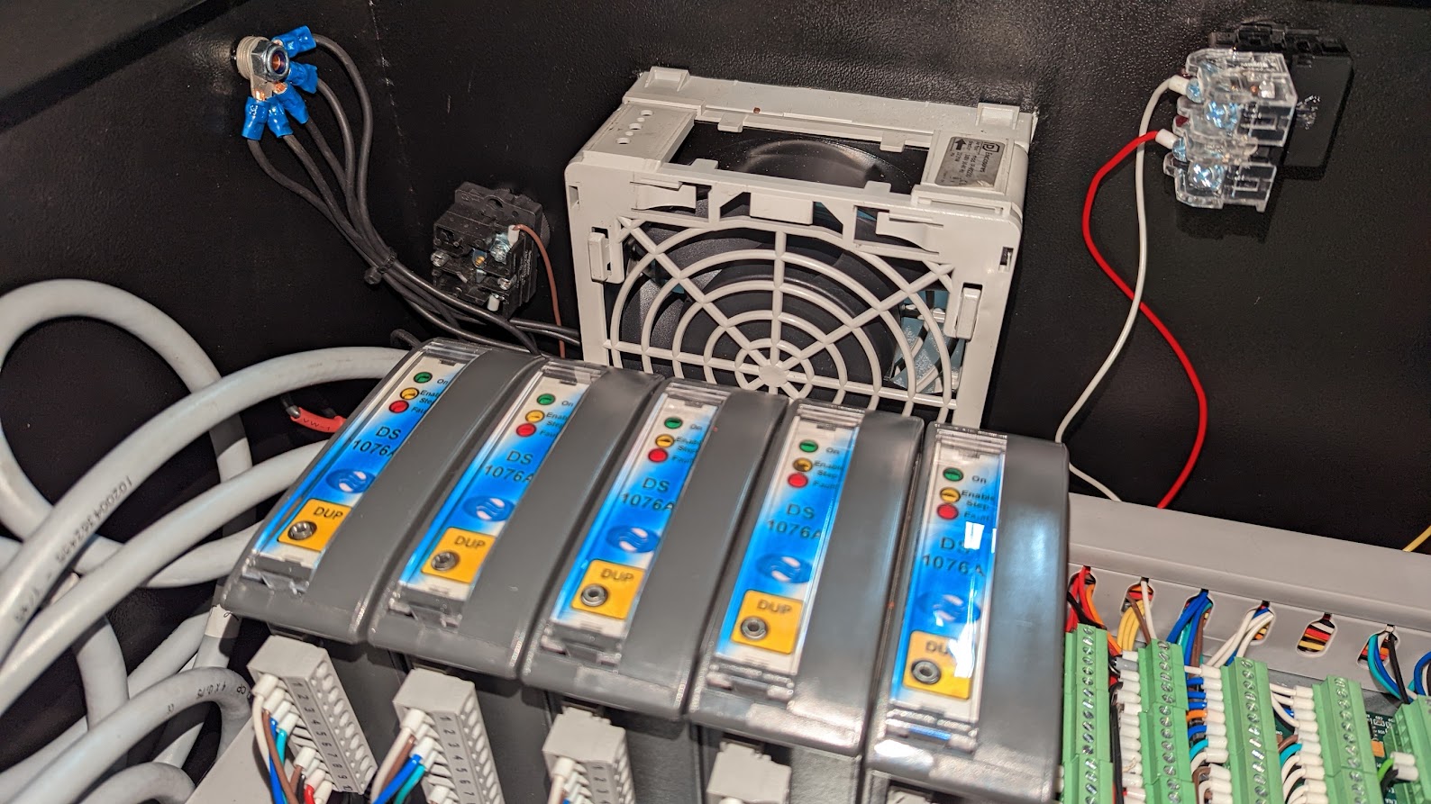
When I've used these drivers, I've also terminated the shield to a copper grounding post on the enclosusre as shown here.
Note we've deliberately chosen steppers over servos in this application (plasma table) to leverage the massive acceleration steppers provide. (5 m/sec/sec or higher)
Attachments:
Please Log in or Create an account to join the conversation.
I guess use of a grounding clamps could be used instead of my pigtails to frame ground.
So best practice for both steppers and servos is not to do any soldering. Yippee!
")
Attachments:
Please Log in or Create an account to join the conversation.
Since the drives look to be insulated from the cabinet's grounded mount plate, connecting the shield with a clamp to the plate won't do you any good as I understand it. You are probably best off just following the instructions in the manual, paying close attention to the "it must be as much short at possible" part.I guess use of a grounding clamps could be used instead of my pigtails to frame ground.
I don't see anything about EMC compliance in the publicly available documentation for those drives. Maybe it's in the User Manual that's behind a registration wall? *doh* Maybe these drives aren't designed to meet any specific EMC standard and controlling EMI is just an afterthought? Or maybe they are controlling the rise times of the motor driver FETs to not produce high frequency EMI in the first place (at the expense of more heat) and have calculated that the pigtail connection of the shield is enough. Who knows?
Please Log in or Create an account to join the conversation.
Yeah I have similarly been scratching my head about how to connect the shield to these old servos:I wouldn't know where to put the screen on my milling spindle. The junction box is in plastic.
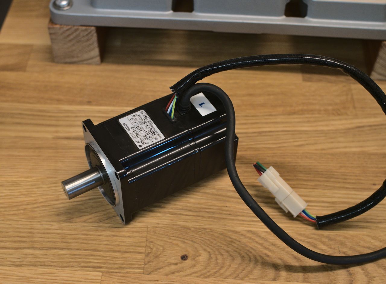
But after reading about how the shield is the return path of common mode noise between motor frame and drive, I think a good solution is to attach the incoming cable shield with a P-clip to the aluminium plate that the motor will be mounted to. That should provide a low impedance path from the motor frame to the shield. I hope. At least that's the best idea I've been able to come up with!
Attachments:
Please Log in or Create an account to join the conversation.
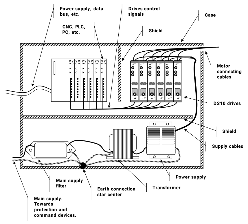
If for a plasma machine, you should attach a seperate ground wire from every motor that is run seperately back to the star ground point. Some industrial quality stepper motors actually have a screw terminal for this purpose. Alternatively use one of the motor mounting bolts. You also need to ensure that these ground wires bridge any motion rails to avoid EMI passing through the rail and its carriage. Hypertherm have a good tech note on grounding which I follow. www.hypertherm.com/Download?fileId=HYP103900&zip=False
Its probably best practice for any motor that does not have a dedicated ground wire.
So I suspect This would explain why Lam do it the way they do. The EMI is drained away by the grounding system.
Please Log in or Create an account to join the conversation.
I'm not sure why you would say that since it's exactly the opposite of what's recommended by the sources I gave earlier. E.g. from the Danfoss document:@avidb, Normally you would leave the shield unattached at the motor and attach it to frame ground at the enclosure.
It is important to realize that the effect of a shielded cable is reduced when only one end is terminated. It is very important to terminate correctly both ends of the motor cable, otherwise interference problems may occur.
Most importantly, the two written sources explain their reasoning in a way that makes sense. Your call...
Which is exactly what you want to avoid since it creates a big current loop for the noise to radiate from. See the Electrical Engineering Portal images. You also want to keep the motor noise away from ground circuitry used by other equipment to which it can otherwise be conducted. You want the noise return path to be through the shield, not through motion rails or paths shared with feedback circuitry.So I suspect This would explain why Lam do it the way they do. The EMI is drained away by the grounding system.
Please Log in or Create an account to join the conversation.

There is a ton of information on the web covering this. Here are just a few examples:
www.edn.com/never-use-pigtails-on-cable-shields/
www.rfemcdevelopment.eu/lv/emc-basics/emc-blog/147-emc-pigtail
In a cabinet one can use a ground busbar like this:
www.phoenixcontact.com/en-au/technologie...-in-control-cabinets
Personally I use P-Clamps and bolt those to busbars or the grounded backplate in the cabinet as those shield clamps can get a bit pricey. The only reason I see why companies like LAM suggest the use of (short) pigtails is to make wiring of their product look "easier".
The installation manual of a name brand VFD is usually a good source for proper grounding techniques.
But att the end of the day it's still a lot better to use shielded cabling with short pigtails than using unshielded cabling.
Edit
Just to be clear, I don't mean to be in anyway authorative about the matter or put anybodies work down. But since this has come up I thought I'd share what I had to learn (sometimes the hard way) in the past.
Please Log in or Create an account to join the conversation.
- Hardware & Machines
- Driver Boards
- How do you pass shielded servo motor cables through the cabinet wall/panel?