Hardware specification of mesa 7c81

Please Log in or Create an account to join the conversation.

ClockMult1 : DCM -- This takes 12 Mhz clkin and multiplies to 96 MHz ClockMed
generic map (
CLKDV_DIVIDE => 2.0,
CLKFX_DIVIDE => 2,
CLKFX_MULTIPLY => 16, -- 16 FOR 96 Mhz
CLKIN_DIVIDE_BY_2 => FALSE,
CLKIN_PERIOD => 20.0,
CLKOUT_PHASE_SHIFT => "NONE",
CLK_FEEDBACK => "1X",
DESKEW_ADJUST => "SYSTEM_SYNCHRONOUS",
Leaving ClockMult0's X2 alone
Note that you need to change the IDROM constants for the clocks for this specific
config so that things like baudrates etc are calculated correctly
Please Log in or Create an account to join the conversation.
- DerBierBaron
- Offline
- New Member
-

- Posts: 1
- Thank you received: 0
Hi PCW,For best signal integrity, (and highest SPI clock rate) you need to
use every ground and power connection on the RPI, or ground
bumping between the RPI and the FPGA card will result in very
poor signal integrity. This is why the 7C80 and 7C81 use the
complete 40 pin connector and connect all grounds plus bypass all
3.3V and 5V RPI power connections on the FPGA card.
I am a new user in the LinuxCNC forums and am looking to convert my previous GRBL machine to run LinuxCNC via Raspberry Pi4, Mesa 7C81 and 7I78 step/dir daughter card. Could you please elaborate a bit on the design of the 7C81?
As far as I've read the 3,3V supply pins from the RPi4 are not used at the 7C81 side or am I mistaken? Most GPIOs aren't used at the 7C81, correct? Only the SPI capable pins are really used to communicate, right?
I am used to powering my RPi4s vie the USB-C connector as there is circuitry on the input side to prevent overvoltage (to some degree), but not via the GPIO-pins and I was wondering if there is any benefit to not connect the Vcc pins (5V and 3.3V I mean)? I thought to only connect every GND pin and the SPI pins to reference GND properly between boards and maybe protect the RPi4 with the included overvoltage circuitry.
If I understand your previous statement correctly my suggested connection method is what you meant by ground bumping, right?
How are the 3.3V and 5V pins bypassed on the FPGA? If the power supply can handle it should I maybe not power the 7C81 via the TB1 (and/or TB2) but only via the USB-C? Is there overvoltage protection on the 7C81 that makes it safe to use the GPIOs as VCC input for the RPi4? Would there be a downside to power both boards in parallel if the same power supply is connected (and capable of doing so)?
Sorry if I'm asking too much at once, but I'm a little excited to get into LinuxCNC

Kind regards,
Klaus
Please Log in or Create an account to join the conversation.
so the RPI can be powered via the 7C81. You could also power the 7C81 from 5V RPI
power (from USB for example) as the 7C81 draws little current .
The 3.3V GPIO connections are bypassed on the 7C81 (so used as additional AC grounds)
but not used for power. This is done because the number of grounds between cards
(both direct and AC coupled) has a profound effect on signal integrity. All GPIO pins are routed
to the FPGA but with standard GCSPI firmware, only the SPI interface 0 pins are used.
Please Log in or Create an account to join the conversation.
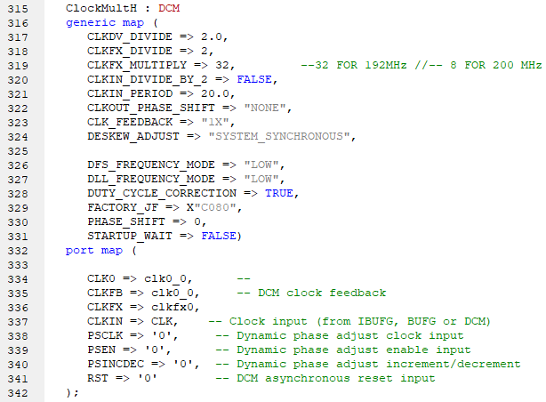
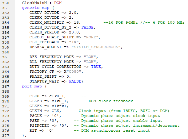
You could certainly get 96 and 192 MHz with:
ClockMult1 : DCM -- This takes 12 Mhz clkin and multiplies to 96 MHz ClockMed
generic map (
CLKDV_DIVIDE => 2.0,
CLKFX_DIVIDE => 2,
CLKFX_MULTIPLY => 16, -- 16 FOR 96 Mhz
CLKIN_DIVIDE_BY_2 => FALSE,
CLKIN_PERIOD => 20.0,
CLKOUT_PHASE_SHIFT => "NONE",
CLK_FEEDBACK => "1X",
DESKEW_ADJUST => "SYSTEM_SYNCHRONOUS",Leaving ClockMult0's X2 aloneNote that you need to change the IDROM constants for the clocks for this specificconfig so that things like baudrates etc are calculated correctly
Okay, I'll try and see if it works. Thanks !!My another approach will be installing 50MHz crystal oscillator. I am also trying to use mesaflash, but I am confused how RPI can detect FPGA ? Every time I run mesflash I got "Board not detected". Also, all I've connected is SPI's signals. I'm powering fpga using USB-JTAG port and in spartan 6 mini they have inbuilt FTDI. So, how can I physically connect JTAG with RPI ? Do I need a converter for this ?Using this command "sudo mesaflash --device 7c81 --addr /dev/spidev0.0 --spi --fix-boot-block --write 7c81_5abobx3d.bit"
Thanks !!
Please Log in or Create an account to join the conversation.
So to program your bitfile (until you get a working config) you will have to use the utility that comes with your board via USB.
Once you have a working bitfile you can use mesaflash.
Mesaflash requires a working mesa bitfile to work.
OK you might be able to use openFPGALoader and using the cable argument ft2232 if when plugged in the usb device has the vid-pid 0x0403:6010 as the FT2232 is connected to the JTAG pins.
Don't be surprised if you can only fit one config on the flash eeprom that comes with your board.
Please Log in or Create an account to join the conversation.
And inside IDROMConst.vhd :
Still not able to run linuxcnc :constant ClockLowC81: integer := 96000000; -- 7C81 low speed clock
constant ClockMedC81: integer := 96000000; -- 7C81 medium speed clock
constant ClockHighC81: integer := 192000000; -- 7C81 high speed clock
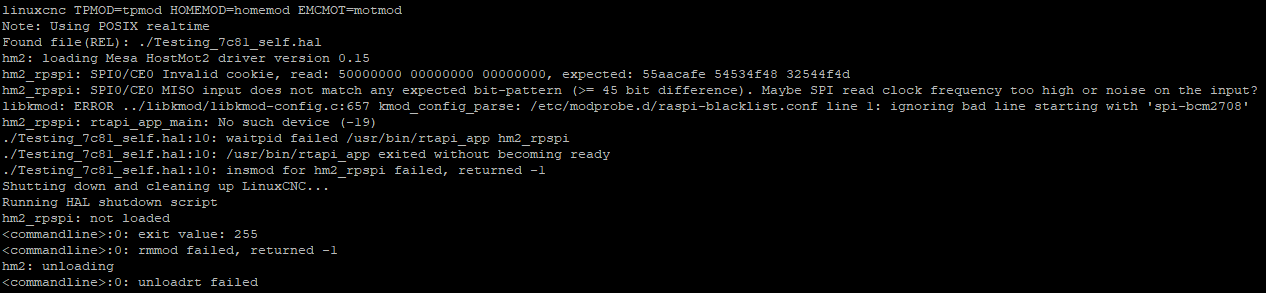
Is there any mistake in changes ?
Thanks !!
Attachments:
Please Log in or Create an account to join the conversation.
Please Log in or Create an account to join the conversation.
I would suggest < 2" maximum cable length and using all GNDs
Please Log in or Create an account to join the conversation.
Thank You soo much !!How long is your cable and do you have all grounds connected?
I would suggest < 2" maximum cable length and using all GNDs
It worked, although I have to install 100MHz crystal oscillator.
Now I have to configure 3 axis CNC machine with spindle using Pncconf. Can you help how to configure ? Cause I have configured using this
Thanks !!
Please Log in or Create an account to join the conversation.