Hardware specification of mesa 7c81
I am trying to implement simply 3-axis cnc-machine with spindle with my spartan-6 fpga and raspberry pi-4 (attaching spartan-6 mini manual for the reference).
I've tried to understand PIN_5ABOBx3D_57.vhd, 7c81spi.ucf & c81_x9card.vhd and made project on ISE 14.7 (changed ucf file according to our spartan-6 pinouts), also created bitstream and flashed it using impact of xilinx. I've also configured linuxcnc using pncconf and edited "loadrt pci" to "loadrt rpspi" & "5i25" to "7c81" in ini and hal file respectively.
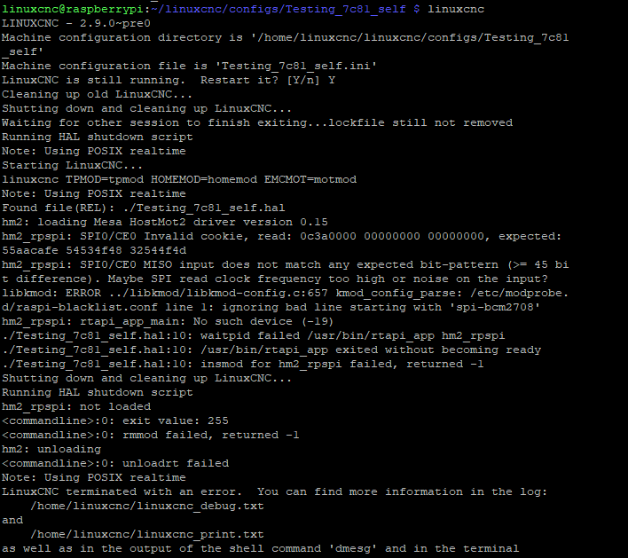
Still facing issue while running linuxcnc. attaching ss of error while running linuxcnc and files of fpga.
Can anyone please help me with this ?
Thanks !!
Attachments:
Please Log in or Create an account to join the conversation.

When the hm2_rpspi driver is loading it is not getting the correct cookie.
This is the section you need to change
   ClockMultH : DCM
   generic map (
      CLKDV_DIVIDE => 2.0,
      CLKFX_DIVIDE => 2,
      CLKFX_MULTIPLY => 8,			-- 8 FOR 200 MHz
      CLKIN_DIVIDE_BY_2 => FALSE,
      CLKIN_PERIOD => 20.0,
      CLKOUT_PHASE_SHIFT => "NONE",
      CLK_FEEDBACK => "1X",
      DESKEW_ADJUST => "SYSTEM_SYNCHRONOUS",

      DFS_FREQUENCY_MODE => "LOW",
      DLL_FREQUENCY_MODE => "LOW",
      DUTY_CYCLE_CORRECTION => TRUE,
      FACTORY_JF => X"C080",
      PHASE_SHIFT => 0,
      STARTUP_WAIT => FALSE)
   port map (

      CLK0 => clk0_0,   	--
      CLKFB => clk0_0,  	-- DCM clock feedback
		CLKFX => clkfx0,
      CLKIN => CLK,    -- Clock input (from IBUFG, BUFG or DCM)
      PSCLK => '0',   	-- Dynamic phase adjust clock input
      PSEN => '0',     	-- Dynamic phase adjust enable input
      PSINCDEC => '0', 	-- Dynamic phase adjust increment/decrement
      RST => '0'        -- DCM asynchronous reset input
   );

  BUFG_inst0 : BUFG
   port map (
      O => fclk,    -- Clock buffer output
      I => clkfx0      -- Clock buffer input
   );

   ClockMultM : DCM
   generic map (
      CLKDV_DIVIDE => 2.0,
      CLKFX_DIVIDE => 2,
      CLKFX_MULTIPLY => 4,			-- 4 FOR 100 MHz
      CLKIN_DIVIDE_BY_2 => FALSE,
      CLKIN_PERIOD => 20.0,
      CLKOUT_PHASE_SHIFT => "NONE",
      CLK_FEEDBACK => "1X",
      DESKEW_ADJUST => "SYSTEM_SYNCHRONOUS",

      DFS_FREQUENCY_MODE => "LOW",
      DLL_FREQUENCY_MODE => "LOW",
      DUTY_CYCLE_CORRECTION => TRUE,
      FACTORY_JF => X"C080",
      PHASE_SHIFT => 0,
      STARTUP_WAIT => FALSE)
   port map (

      CLK0 => clk0_1,   	--
      CLKFB => clk0_1,  	-- DCM clock feedback
		CLKFX => clkfx1,
      CLKIN => CLK,    -- Clock input (from IBUFG, BUFG or DCM)
      PSCLK => '0',   	-- Dynamic phase adjust clock input
      PSEN => '0',     	-- Dynamic phase adjust enable input
      PSINCDEC => '0', 	-- Dynamic phase adjust increment/decrement
      RST => '0'        -- DCM asynchronous reset input
   );

  BUFG_inst1 : BUFG
   port map (
      O => clklow,    -- Clock buffer output
      I => clkfx1      -- Clock buffer input
   );

  -- End of DCM_inst instantiation
For a 50Mhz clock (std on Mesa boards) the base clock is initially divided by 2 and the multiplied by the following to get the desired frequencies. As you seem to e using a 12MHz clock I'm not too sure the actual values you will need, hopefully PCW will have the answers.
CLKFX_MULTIPLY => 8, -- 8 FOR 200 MHz
CLKFX_MULTIPLY => 4, -- 4 FOR 100 MHz
When using a 100Mhz clock
CLKFX_MULTIPLY => 4, -- 4 FOR 200 MHz
CLKFX_MULTIPLY => 2, -- 2 FOR 100 MHz
And when using a 25MHz clock
CLKFX_MULTIPLY => 16, -- 16 FOR 200 MHz
CLKFX_MULTIPLY => 8, -- 8 FOR 100 MHz
Please Log in or Create an account to join the conversation.
Please Log in or Create an account to join the conversation.
What if I install 100MHz oscillator in my board and then edit code according to you, will it work ?
Also, I am not so sure about my ini and hal files as its new to me (attaching ini and hal file for the reference).
Thanks !!
Attachments:
Please Log in or Create an account to join the conversation.
Please Log in or Create an account to join the conversation.
Yes, I've connected COM_SPICLK, COM_SPIIN, COM_SPIOUT & COM_SPICS to the rpi's GPIO11(23), GPIO10(19), GPIO9(21) & GPIO8(24) respectively. Also I have them on fpga's GPIOs so I didn't change them.Another thing I'm not entirely 100% about is whether COM_SPICLK, COM_SPIIN & COM_SPIOUT have to be on the same "portion" of a bank.
Please Log in or Create an account to join the conversation.
With the clock yeah I run a 100MHz clock or if it's just as easy to use a 50MHz crystal I go with that, saves the amount of code mods you'll have to make.
Another thing I had to do on one of my boards is change the SPI flash to 16MBit, I think, to be able to have a fallback config.
Also make sure that you are correctly translating 5v to 3.3v as the Spartan 6 can only take ~4v max at the inputs, but if you work with 3.3v being the max you should be good.
I use SN74CBT3245 FET bus Switches and have the Vcc at 4.2 as you get a ~3.3v on the FPGA side and have the "world side" pulled up to 5v.
You may have to play around with spiclk_rate, depending on the connection from your RPi to you dev board, it may not run at 32Mhz. With 100mm Dupont cables the best I was seeing was about 15.625 MHz. Once I had my PCB designed and using a cable with a GND between each signal I was able to run at about 20.833 MHz.
IMHO unless you have the clocks setup right I don't think playing around with ini & hal files will help much.
Please Log in or Create an account to join the conversation.
forum.linuxcnc.org/27-driver-boards/3639...-as-a-7i90hd?start=0
Running 7i90 as smart serial remote board, this was a pretty involved one.
forum.linuxcnc.org/27-driver-boards/4995...7i90hd-now-a-success
forum.linuxcnc.org/38-general-linuxcnc-q...-schematics-for-7c81
forum.linuxcnc.org/27-driver-boards/49772-7c81-bitfile
I've also been playing around with EPP interafce as well, not a bad option in you a PC with on board parallel port but latency isn't the best.
Hostmot2 firmware is pretty easy to get going on man spartan 6 boards, so far I've had success with a Mimas Spartan 6 board, linsin rv901T, linsin MINI901 (can't find any more on a ddr2 module), the Spartan 6 dev board mentioned in the 7i90 thread and next victim will be a linsin RV907.
Please Log in or Create an account to join the conversation.
Okay I understand this. Thanks !!With the clock yeah I run a 100MHz clock or if it's just as easy to use a 50MHz crystal I go with that, saves the amount of code mods you'll have to make.
So, what I understand is that I have to design PCB to achieve high frequency, right ?You may have to play around with spiclk_rate, depending on the connection from your RPi to you dev board, it may not run at 32Mhz. With 100mm Dupont cables the best I was seeing was about 15.625 MHz. Once I had my PCB designed and using a cable with a GND between each signal I was able to run at about 20.833 MHz.
IMHO unless you have the clocks setup right I don't think playing around with ini & hal files will help much.
Also do I need to connect any extra GPIO b/w rpi and fpga ? As of now I am only connecting SPI signals using Dupont cables.
Please Log in or Create an account to join the conversation.

use every ground and power connection on the RPI, or ground
bumping between the RPI and the FPGA card will result in very
poor signal integrity. This is why the 7C80 and 7C81 use the
complete 40 pin connector and connect all grounds plus bypass all
3.3V and 5V RPI power connections on the FPGA card.
Please Log in or Create an account to join the conversation.