Flash a XC6SLX9 dev board as a 7i90HD
- gtt38
- Offline
- Senior Member
-

Less
More
- Posts: 79
- Thank you received: 4
16 Apr 2019 10:54 - 16 Apr 2019 10:55 #130972
by gtt38
Flash a XC6SLX9 dev board as a 7i90HD was created by gtt38
Hi
I'm looking to create a small and cheap embedded solution for Linuxcnc on a Raspberry to drive 3D printers. I was thinking to create a shield board for it based on a Spartan 6 using the SPI port (like the 7i90HD).
I found this little dev board for only 17$ on aliexpress it's a XC6SLX9 :
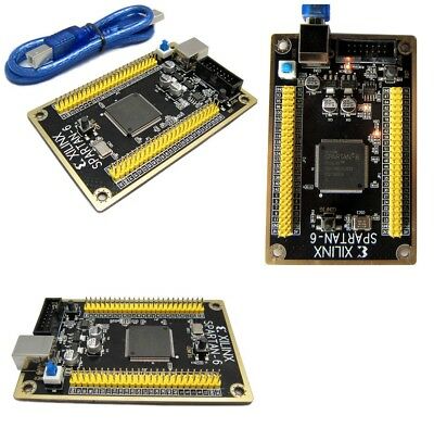
There is an M25P40 (4 Mbit) onboard.
Do you think it's possible to do that ? Is it legal (maybe the firmware license ?)
Thanks
I'm looking to create a small and cheap embedded solution for Linuxcnc on a Raspberry to drive 3D printers. I was thinking to create a shield board for it based on a Spartan 6 using the SPI port (like the 7i90HD).
I found this little dev board for only 17$ on aliexpress it's a XC6SLX9 :
There is an M25P40 (4 Mbit) onboard.
Do you think it's possible to do that ? Is it legal (maybe the firmware license ?)
Thanks
Attachments:
Last edit: 16 Apr 2019 10:55 by gtt38.
Please Log in or Create an account to join the conversation.
- PCW
-

- Offline
- Moderator
-

Less
More
- Posts: 17991
- Thank you received: 5281
16 Apr 2019 14:33 #130977
by PCW
Replied by PCW on topic Flash a XC6SLX9 dev board as a 7i90HD
Yes, you should be able to do this, the HostMot2 firmware is open source.
Basically you would need to generate 3 card specific files for the Hostmot2 source:
XXXXcard.vhd (card specific info like number of GPIO etc)
XXXX.ucf (physical pin mapping)
PIN_XXXX.vhd (logical pin mapping, there can be many of these, and these are not card specific but rather number_of_GPIO_pin specific)
You can use these 7i90 versions of the above files as a starting point
i90_x9card.vhd
7i90spi.ucf
(plus any of the PIN_XXXX.vhd files)
The following user(s) said Thank You: gtt38, tuzki
Please Log in or Create an account to join the conversation.
- gtt38
- Offline
- Senior Member
-
Less
More
- Posts: 79
- Thank you received: 4
18 Apr 2019 14:18 - 18 Apr 2019 14:21 #131162
by gtt38
Replied by gtt38 on topic Flash a XC6SLX9 dev board as a 7i90HD
Thanks so much PCW
Do you think that i will need to change the M25P40 for a M25P80 to have a dual configuration file ? How can i switch from both config ?
Which chip is used by Mesa to level to 5V ?
I'm looking to create a "shield" for this Xilinx dev board with x3 50 pins idc.
Do you think that i will need to change the M25P40 for a M25P80 to have a dual configuration file ? How can i switch from both config ?
Which chip is used by Mesa to level to 5V ?
I'm looking to create a "shield" for this Xilinx dev board with x3 50 pins idc.
Attachments:
Last edit: 18 Apr 2019 14:21 by gtt38.
Please Log in or Create an account to join the conversation.
- PCW
-
- Offline
- Moderator
-
Less
More
- Posts: 17991
- Thank you received: 5281
18 Apr 2019 14:38 #131165
by PCW
Replied by PCW on topic Flash a XC6SLX9 dev board as a 7i90HD
The 7I90 switches configs by having two flash chips, This is not strictly necessary.
You could select between configurations using ICAP once a basic configuration is loaded (you can do this currently with mesaflash)
If you are going to bother to replace the flash chip, I would use a 16 Mbit chip
(Winbond 16 Mbit chips are in the $0.30 - $0.50 region)
We use Onsemi (TI has these also) 16211 chips (Onsemi PN is FST16211) on all I/O pins.
These chips provide 5V tolerance (24 pins each), but the outputs still only drive to 3.3V. You _can_ get 5V swing on the outputs by putting pullup resistors to 5V on the external interface side of the 16211's
The following user(s) said Thank You: tivoi
Please Log in or Create an account to join the conversation.
- gtt38
- Offline
- Senior Member
-
Less
More
- Posts: 79
- Thank you received: 4
21 Apr 2019 13:05 - 21 Apr 2019 13:11 #131390
by gtt38
Replied by gtt38 on topic Flash a XC6SLX9 dev board as a 7i90HD
Thank you again, if i understood clearly what you are saying, the only thing that i need to change is the Eprom pin assignement.
my I90_x9card.vhd (no change)
Now 7i90spi.ucf i need to declare my eprom
but there is 2 spi ports on the 7i90spi.ucf :
Which one is for the eprom and which one for the raspberry ?
Is it for the JTAG tool ?
my I90_x9card.vhd (no change)
library IEEE;
use IEEE.std_logic_1164.all;  -- defines std_logic types
use IEEE.STD_LOGIC_ARITH.ALL;
use IEEE.STD_LOGIC_UNSIGNED.ALL;

use work.IDROMConst.all;
package i90_x9card is
		-- 7I90 x9 card specific info
		constant ClockHigh: integer := ClockHigh90;
		constant ClockMed: integer := ClockMed90;
		constant ClockLow: integer := ClockLow90;
		constant BoardNameLow : std_Logic_Vector(31 downto 0) := BoardNameMESA;
		constant BoardNameHigh : std_Logic_Vector(31 downto 0) := BoardName7I90;
		constant FPGASize: integer := 9;
		constant FPGAPins: integer := 144;
		constant IOPorts: integer := 3;
		constant IOWidth: integer := 72;
		constant PortWidth: integer := 24;
		constant LIOWidth: integer := 6;
		constant LEDCount: integer := 2;
		constant	SepClocks: boolean := true;
		constant OneWS: boolean := false;
end package i90_x9card;
Now 7i90spi.ucf i need to declare my eprom
but there is 2 spi ports on the 7i90spi.ucf :
NET	"COM_SPICLK"	LOC ="P55"	 | IOSTANDARD = LVTTL;
NET	"COM_SPIIN"	LOC ="P56"	 | IOSTANDARD = LVTTL;
NET	"COM_SPIOUT"	LOC ="P57"	 | IOSTANDARD = LVTTL | DRIVE = 4 | SLEW = FAST ;
NET "COM_SPICS" LOC ="P58" | IOSTANDARD = LVTTL;
NET "SPICS" LOC ="P38" | IOSTANDARD = LVTTL | DRIVE = 4 | SLEW = SLOW ;
NET "SPIIN" LOC ="P65" | IOSTANDARD = LVTTL;
NET "SPIOUT" LOC ="P64" | IOSTANDARD = LVTTL | DRIVE = 4 | SLEW = SLOW ;
NET "SPICLK" LOC ="P70" | IOSTANDARD = LVTTL | DRIVE = 4 | SLEW = SLOW ;Which one is for the eprom and which one for the raspberry ?
Is it for the JTAG tool ?
#NET	"FPGATMS"	LOC ="P107"	 ;
#NET	"FPGATDI"	LOC ="P110"	 ;
#NET	"FPGATDO"	LOC ="P106"	 ;
#NET "FPGACLK" LOC ="P109" ;
Last edit: 21 Apr 2019 13:11 by gtt38.
Please Log in or Create an account to join the conversation.
- PCW
-
- Offline
- Moderator
-
Less
More
- Posts: 17991
- Thank you received: 5281
21 Apr 2019 13:24 #131391
by PCW
Replied by PCW on topic Flash a XC6SLX9 dev board as a 7i90HD
You cannot change the EEPROM pin assignment if you expect the FPGA to load its configuration on startup (the configuration SPI pins are always on the same FPGA pins)
The host interface are the "COM_SPIXX" pins. These can be moved to any pins
with the limitation that COM_SPICLK must be on a GCLK pin
And yes the FPGAXXXX pins are the JTAG interface
You will also need a clock, the 7I90 assumes 50 MHz
The host interface are the "COM_SPIXX" pins. These can be moved to any pins
with the limitation that COM_SPICLK must be on a GCLK pin
And yes the FPGAXXXX pins are the JTAG interface
You will also need a clock, the 7I90 assumes 50 MHz
Please Log in or Create an account to join the conversation.
- gtt38
- Offline
- Senior Member
-
Less
More
- Posts: 79
- Thank you received: 4
21 Apr 2019 14:34 - 21 Apr 2019 14:42 #131398
by gtt38
SO how can i put a config file ? in the FPGA itself ?
There is a clock onboard, it's a 50Mhz on pin 55 (it's a 25Mhz on the schematics)
so i have to modify this line :to this :
I'm downloading the ISE 13.4 to compile the firmware.
Replied by gtt38 on topic Flash a XC6SLX9 dev board as a 7i90HD
You cannot change the EEPROM pin assignment if you expect the FPGA to load its configuration on startup (the configuration SPI pins are always on the same FPGA pins)
SO how can i put a config file ? in the FPGA itself ?
You will also need a clock, the 7I90 assumes 50 MHz
There is a clock onboard, it's a 50Mhz on pin 55 (it's a 25Mhz on the schematics)
so i have to modify this line :
NET "CLK" LOC ="P50" | IOSTANDARD = LVTTL | DRIVE = 4 | SLEW = SLOW ;NET "CLK" LOC ="P55" | IOSTANDARD = LVTTL | DRIVE = 4 | SLEW = SLOW ;I'm downloading the ISE 13.4 to compile the firmware.
Last edit: 21 Apr 2019 14:42 by gtt38.
Please Log in or Create an account to join the conversation.
- PCW
-
- Offline
- Moderator
-
Less
More
- Posts: 17991
- Thank you received: 5281
21 Apr 2019 15:47 - 21 Apr 2019 15:50 #131403
by PCW
Replied by PCW on topic Flash a XC6SLX9 dev board as a 7i90HD
Yes, you change the ucf file to change the pins for the clock source
(you will likely have to change al the GPIO assignments to make sense
with the I/O connector wiring also)
Is this a 144 pin package? (I was assuming that), if so its SPI configuration FPGA pins
must be on 38,64,65,70 or it will not work
(you will likely have to change al the GPIO assignments to make sense
with the I/O connector wiring also)
Is this a 144 pin package? (I was assuming that), if so its SPI configuration FPGA pins
must be on 38,64,65,70 or it will not work
Last edit: 21 Apr 2019 15:50 by PCW.
Please Log in or Create an account to join the conversation.
- gtt38
- Offline
- Senior Member
-
Less
More
- Posts: 79
- Thank you received: 4
21 Apr 2019 17:34 #131410
by gtt38
Replied by gtt38 on topic Flash a XC6SLX9 dev board as a 7i90HD
Yep 144
This dev board is really simple to let a maximum of pins available.
it seems to match on my board exactly like a 7i90. 38,64,65,70 just tested, these chinese made an error on the schematics for the pin 65.
I ve 2 leds on pin 87,88 and an another one on pin 71
This dev board is really simple to let a maximum of pins available.
it seems to match on my board exactly like a 7i90. 38,64,65,70 just tested, these chinese made an error on the schematics for the pin 65.
I ve 2 leds on pin 87,88 and an another one on pin 71
Please Log in or Create an account to join the conversation.
- AnnoyingMutt
-

- Visitor
-

22 Apr 2019 00:41 #131434
by AnnoyingMutt
Replied by AnnoyingMutt on topic Flash a XC6SLX9 dev board as a 7i90HD
Oh great another dev board I wanna get just to play with
Actually this is an interesting thread.
Actually this is an interesting thread.
Please Log in or Create an account to join the conversation.
Moderators: PCW, jmelson
Time to create page: 0.747 seconds