Hardinge HC Bandit Retrofit

19 Mar 2017 19:48 #89899
by andypugh
Replied by andypugh on topic Hardinge HC Bandit Retrofit
You will probably need to power-down and power up the PC to boot the card with the new firmware.
Please Log in or Create an account to join the conversation.

19 Mar 2017 20:18 #89900
by PCW
Replied by PCW on topic Hardinge HC Bandit Retrofit
or use the
sudo mesaflash --device 5i24 --reload
option
sudo mesaflash --device 5i24 --reload
option
Please Log in or Create an account to join the conversation.
19 Mar 2017 20:55 #89902
by mclausen
Replied by mclausen on topic Hardinge HC Bandit Retrofit
I had done a power down before flashing, and verified the flash.
I swapped the ribbon cables between the 7I37 and the 7I42, and now I am getting encoder pins!!
Apparently it did not want to assign any encoder pins to the 7I37.
One issue is that my 7I49 is plugged into P1 on the 5I24 and the file shows it as P4 and the others as P3 and P2. The board drawing doesn't show a P2. Should I move the 7I49 cable?
Please Log in or Create an account to join the conversation.
19 Mar 2017 21:18 #89906
by PCW
Replied by PCW on topic Hardinge HC Bandit Retrofit
The 7I49 is on the GPIO 0..23 pins (P4)
The 7I42/encoder is on the GPIO 24..47 pins = middle connector (P3)
and the 7I37COM should be on the GPIO 48..71 pins (P2 on a a 5I24, P1 on a 6I24)
The 7I42/encoder is on the GPIO 24..47 pins = middle connector (P3)
and the 7I37COM should be on the GPIO 48..71 pins (P2 on a a 5I24, P1 on a 6I24)
Please Log in or Create an account to join the conversation.
19 Mar 2017 21:37 #89907
by andypugh
P1 is the PCI connector itself I think.
www.mesanet.com/pdf/parallel/5i24man.pdf
Shows P2 P3 and P4 as the pin headers.
Replied by andypugh on topic Hardinge HC Bandit Retrofit
One issue is that my 7I49 is plugged into P1 on the 5I24 and the file shows it as P4 and the others as P3 and P2. The board drawing doesn't show a P2. Should I move the 7I49 cable?
P1 is the PCI connector itself I think.
www.mesanet.com/pdf/parallel/5i24man.pdf
Shows P2 P3 and P4 as the pin headers.
Please Log in or Create an account to join the conversation.
27 May 2017 19:03 - 27 May 2017 21:27 #93716
by mclausen
Replied by mclausen on topic Hardinge HC Bandit Retrofit
After some delay, I finally made some more progress on this retrofit.
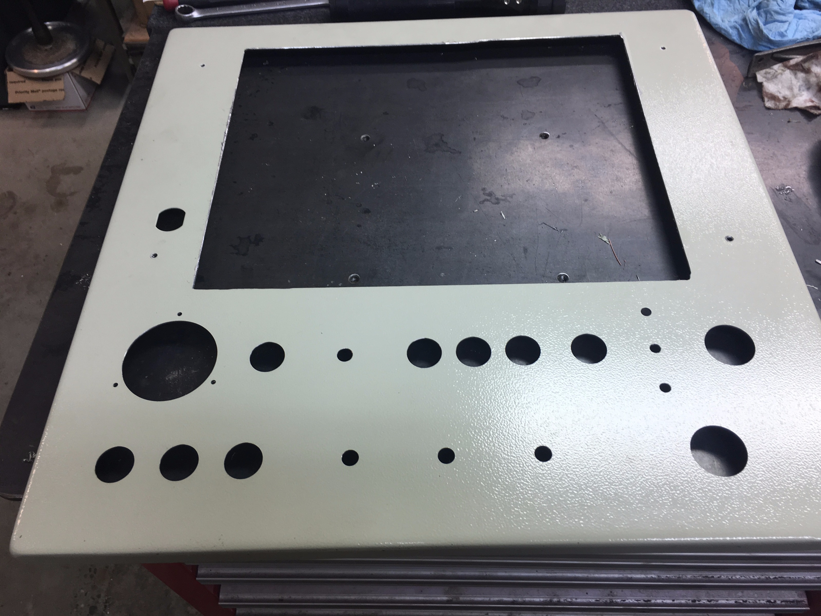
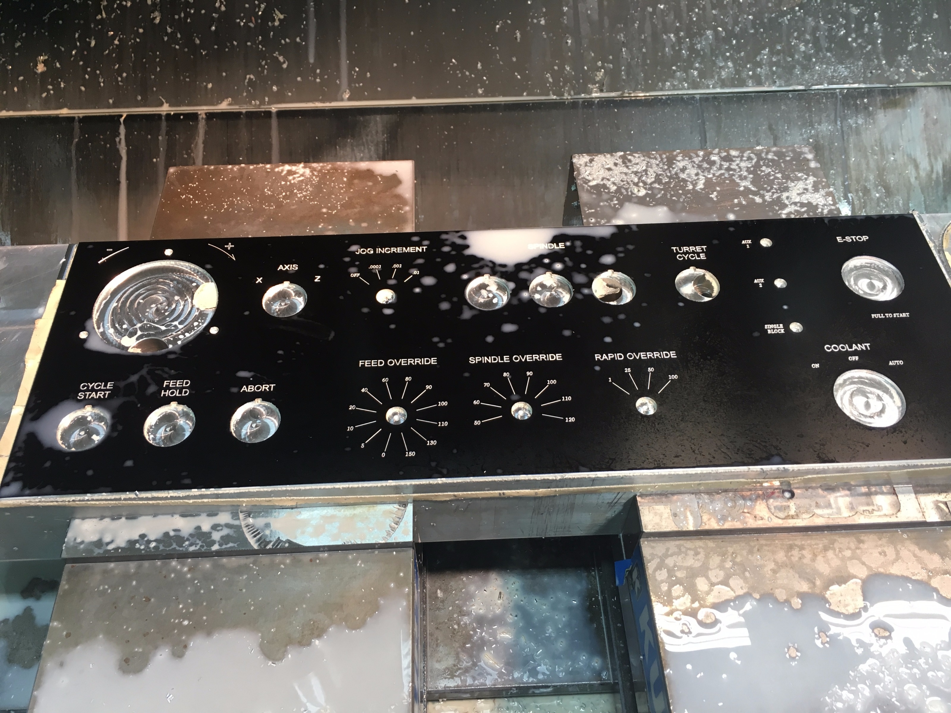
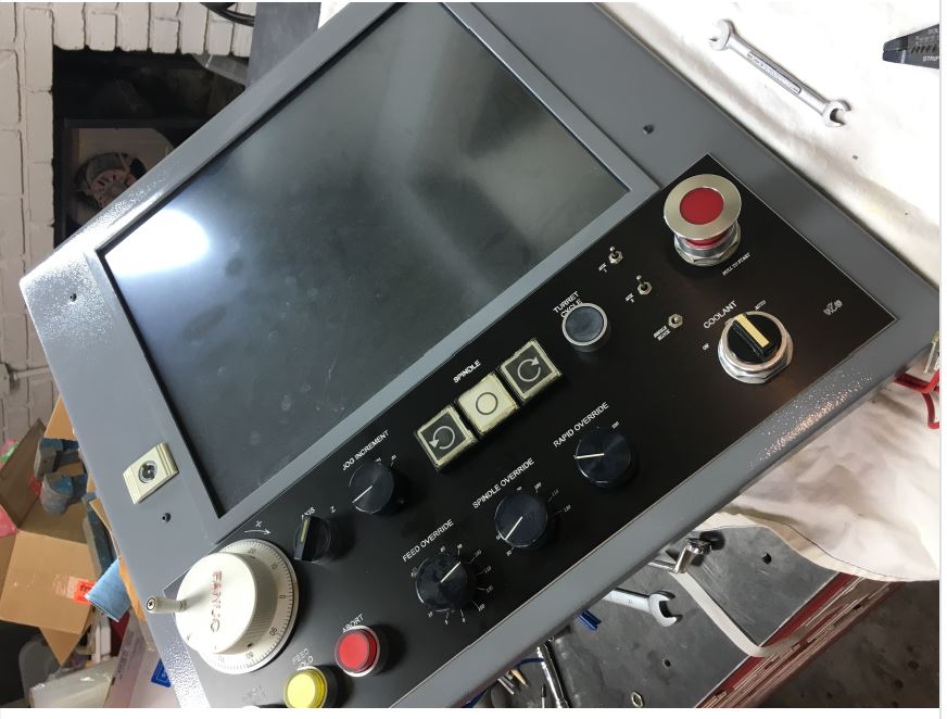
I bought an electrical box, and machined the door to fit the touch screen, and controls.
I needed labels on the panel, so I bought an anodized aluminum sheet, and engraved into it. The controls are mounted, and I started the wiring.
Now I have some basic questions on connecting to the Mesa boards. This is probably so basic, that I haven't been able to find any discussion on it.
How do I wire the control switches to the boards? Can I wire 5V to all the far sides of the switches, and the other side of each switch directly to the + input terminal? Do I need to add pull up resistors?
What about wiring relays? Does the ground side of the coil wire directly to the + I/O terminal on the board?
If I use the 5V power connection to the boards does it need to be from a separate power supply than the voltage on the switches to prevent defeating the isolation?
Thanks
Last edit: 27 May 2017 21:27 by andypugh.
Please Log in or Create an account to join the conversation.
27 May 2017 21:59 #93718
by andypugh
Replied by andypugh on topic Hardinge HC Bandit Retrofit
Assuming you are talking about the 7i37
The inputs are opto-isolators, so you need to think in terms of current flowing into the IN+ terminal and out of the IN- terminal of each input pair. The 7i37 is good for voltages from 5V to 24V, and if you can use 24V it is possibly more reliable to do so.
Each input is isolated, so that you can wire in different ways and at different voltages for each input.
One way to wire would be to daisy-chain +24V to each switch, then take a wire from each switch to the IN+ terminals of the 7i37, then daisy-chain a 0V wire to each IN- and back to the 0V line.
Or you can daisy-chain +24 to each IN+, run a wire to each switch, and have each switch connect to 0V.
I have done all of the above wiring this 7i64 You can see that some inputs are wired with a daisy-chained 0V (black) and others with daisy-chained 5V(red) 12V(yellow) or 24V (orange)
Please Log in or Create an account to join the conversation.
27 May 2017 23:36 #93731
by mclausen
Replied by mclausen on topic Hardinge HC Bandit Retrofit
Thanks Andy.
That helps. I am planning to use the 7I37 with 24V for everything on the machine, relays/ limit switches/ etc. Then for the control panel switches and encoders use the 7I42 with 5v. I assume these would wire the same way?
That helps. I am planning to use the 7I37 with 24V for everything on the machine, relays/ limit switches/ etc. Then for the control panel switches and encoders use the 7I42 with 5v. I assume these would wire the same way?
Please Log in or Create an account to join the conversation.
28 May 2017 00:08 #93733
by andypugh
I don't think so, no. The 7i42 seems to have unipolar voltage inputs.
www.mesanet.com/pdf/parallel/7i42man.pdf
There is a GND paired with each input pin, but that isn't equivalent to the IN- pin on the 7i37.
I think that you need to configure the GPIO In HAL to match the input/output modes of the attached boards,
linuxcnc.org/docs/2.7/html/man/man9/host...eral%20Purpose%20I/O
In input mode the pins are weakly pulled high. So on the 7i42 you can wire a switch directly between the input and GND if that is convenient. Otherwise you can connect a generic 5V / 0V IO pin to the input, and make sure that at least one GND is common to the 0V reference of the driving device. depending on the driving device you might need pull-up or pull-down resistors. What are you actually connecting to the 7i42?
Replied by andypugh on topic Hardinge HC Bandit Retrofit
Thanks Andy.
That helps. I am planning to use the 7I37 with 24V for everything on the machine, relays/ limit switches/ etc. Then for the control panel switches and encoders use the 7I42 with 5v. I assume these would wire the same way?
I don't think so, no. The 7i42 seems to have unipolar voltage inputs.
www.mesanet.com/pdf/parallel/7i42man.pdf
There is a GND paired with each input pin, but that isn't equivalent to the IN- pin on the 7i37.
I think that you need to configure the GPIO In HAL to match the input/output modes of the attached boards,
linuxcnc.org/docs/2.7/html/man/man9/host...eral%20Purpose%20I/O
In input mode the pins are weakly pulled high. So on the 7i42 you can wire a switch directly between the input and GND if that is convenient. Otherwise you can connect a generic 5V / 0V IO pin to the input, and make sure that at least one GND is common to the 0V reference of the driving device. depending on the driving device you might need pull-up or pull-down resistors. What are you actually connecting to the 7i42?
Please Log in or Create an account to join the conversation.
28 May 2017 01:01 #93735
by mclausen
Replied by mclausen on topic Hardinge HC Bandit Retrofit
The 7I42 would connect to the spindle encoder, the MPG encoder, and all the panel switches.
Please Log in or Create an account to join the conversation.
Moderators: cncbasher
Time to create page: 0.536 seconds