How to configure the 7i77 electronic board to always start with a + 10 V ?

More
1 year 9 months ago #319840 by programador
How to configure the 7i77 electronic board to always start with a positive output of 10 volts before home referencing?

Good afternoon everyone, please, I need help with the following situation:

Just to give an example of a stepper motor drive device, when we connect the machine is enabled or amplifier enable input, it physically stops the motor with power to the coils and only moves when there is a Step and Dir pulse, that is, the axis does not move while the machine is on.
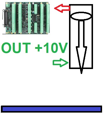
Unfortunately, what I am controlling is not a simple stepper motor, and neither is a Step and Dir pulse used. In my case, I am analogically controlling a hydraulic cylinder in the z-axis movement with the 7i77 electronic board.

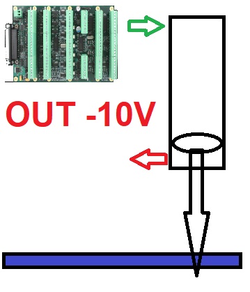
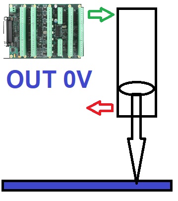
This hydraulic cylinder, when the machine's hydraulic pump is turned on, slowly descends on its own, due to the pressure and the force of gravity itself. To keep it high, it is necessary to press jog + on the Z axis, which injects positive voltage and causes the hydraulic cylinder to rise, but as the analog output returns to zero, the cylinder descends gradually, unlike a stepper motor that remains locked until further notice. In other words, you have to keep pressing the jog + button on the z axis to keep it high.

below illustration:

1 - initial situation before axis home


2- jog +Z situation


3- jog situation -Z


below video demonstration


This situation in the video may show that when moving the tool wheel, it will collide with the Z axis.


To avoid such a collision, I need the Z axis in the case of the 7i77 board output to always have a positive output of +10 volts, this before the home position and before running the g-code program, but when running the g-code program, it will have to obey the commands, when stopping the g-code, it will return to +10 volts. I accept any help or suggestion, I thank everyone who can contribute.

How to configure the 7i77 electronic board to always start with a positive output of 10 volts before home referencing?
 

Please Log in or Create an account to join the conversation.

More
1 year 9 months ago #319842 by PCW
Not quite sure I understand. the position feedback should work whenever LinuxCNC is running
so is seems you should just set the position to retract the head at the end of the Gcode.
In addition the initial Z position should be in the retracted position.


The following user(s) said Thank You: programador

Please Log in or Create an account to join the conversation.

More
1 year 9 months ago #319852 by programador
Thank you for your response.
Yes, you are correct. The position feedback should function properly as long as LinuxCNC is running, so I just need to set the position to retract the head at the end of the G-code, and the initial Z position should be in the retracted state.
However, when starting the machine, the process must be done manually to ensure that the Z-axis is retracted, preventing a potential mechanical issue where the Z-axis could be extended and collide with the punches.
How can I ensure that the Z-axis is retracted before executing the G-code program?

Please Log in or Create an account to join the conversation.

More
1 year 9 months ago #319855 by tommylight
Is it setup as a normal axis?
Adding a switch and using it for homing would work in that case.
Adding the switch would be advisable in any case and set it in hal so it does not allow anything to move if the cylinder is not in the upper position.
The following user(s) said Thank You: programador

Please Log in or Create an account to join the conversation.

More
1 year 9 months ago #319856 by tommylight
The following user(s) said Thank You: programador

Please Log in or Create an account to join the conversation.

More
1 year 9 months ago #319858 by programador
Thanks for the feedback, good suggestion, but since I'm very late on this project, physically installing a sensor will take more time and I don't know if the client will accept it on the next visit. Your idea helped me to try a different way, maybe never tried before in LinuxCNC, which would be to take the analog voltage reading from the inductive sensor that is present and already part of the original machine and create a logical ladder to compare the voltage from zero to 10V where 8.6 volts would be the virtual limit switch. With your experience, do you think it is possible to use an analog reading and determine certain thresholds to turn on and off a bit memory in the ladder and use it as a limit switch?

Please Log in or Create an account to join the conversation.

Time to create page: 0.119 seconds
Powered by Kunena Forum