Remora - ethernet NVEM / EC300 / EC500 cnc board
- scotta
-
 Topic Author
- Offline
- Platinum Member
-

Less
More
- Posts: 956
- Thank you received: 486
16 Oct 2022 21:32 - 16 Oct 2022 21:35 #254265
by scotta
Replied by scotta on topic Remora - ethernet NVEM / EC300 / EC500 cnc board
I installed an old v6.60 version of J-Link to see if it was something to do with the clone detection. Unfortunately the same result using the JFlash GUI.
So, I tried the command line J-Link Commander tool, and Success!!! Original firmware has been read out from the Flash and put away in a safe place.") And better news is that the firmware does not look to be secured with all text strings visible in the bin file.
And better news is that the firmware does not look to be secured with all text strings visible in the bin file.
Looks like we have a way for people to flash the firmware, even if it is via the command line.
Next step is to do a dummy test program in Flash to ensure the tool chain, and then to remove the iMX RT1052 from the board.
Type "connect" to establish a target connection, '?' for help
J-Link>connect
Please specify device / core. <Default>: MIMXRT1052CVL5B
Type '?' for selection dialog
Device>MIMXRT1052CVL5B
Please specify target interface:
J) JTAG (Default)
S) SWD
T) cJTAG
TIF>s
Specify target interface speed [kHz]. <Default>: 4000 kHz
Speed>
Device "MIMXRT1052CVL5B" selected.
Connecting to target via SWD
InitTarget() start
InitTarget()
_TargetHalt: CPU halted
InitTarget() end
Found SW-DP with ID 0x0BD11477
Scanning AP map to find all available APs
AP[1]: Stopped AP scan as end of AP map has been reached
AP[0]: AHB-AP (IDR: 0x04770041)
Iterating through AP map to find AHB-AP to use
AP[0]: Core found
AP[0]: AHB-AP ROM base: 0xE00FD000
CPUID register: 0x411FC271. Implementer code: 0x41 (ARM)
Found Cortex-M7 r1p1, Little endian.
FPUnit: 8 code (BP) slots and 0 literal slots
CoreSight components:
ROMTbl[0] @ E00FD000
ROMTbl[0][0]: E00FE000, CID: B105100D, PID: 000BB4C8 ROM Table
ROMTbl[1] @ E00FE000
ROMTbl[1][0]: E00FF000, CID: B105100D, PID: 000BB4C7 ROM Table
ROMTbl[2] @ E00FF000
ROMTbl[2][0]: E000E000, CID: B105E00D, PID: 000BB00C SCS-M7
ROMTbl[2][1]: E0001000, CID: B105E00D, PID: 000BB002 DWT
ROMTbl[2][2]: E0002000, CID: B105E00D, PID: 000BB00E FPB-M7
ROMTbl[2][3]: E0000000, CID: B105E00D, PID: 000BB001 ITM
ROMTbl[1][1]: E0041000, CID: B105900D, PID: 001BB975 ETM-M7
ROMTbl[1][2]: E0042000, CID: B105900D, PID: 004BB906 CTI
ROMTbl[0][1]: E0040000, CID: B105900D, PID: 000BB9A9 TPIU-M7
ROMTbl[0][2]: E0043000, CID: B105F00D, PID: 001BB101 TSG
Cache: Separate I- and D-cache.
I-Cache L1: 32 KB, 512 Sets, 32 Bytes/Line, 2-Way
D-Cache L1: 32 KB, 256 Sets, 32 Bytes/Line, 4-Way
Cortex-M7 identified.
J-Link>Halt
PC = 60006226, CycleCnt = 00000000
R0 = 00000000, R1 = 00000000, R2 = 00000001, R3 = 00000002
R4 = 03FFFF10, R5 = 402D8000, R6 = 20200F0C, R7 = 00000000
R8 = 00000001, R9 = 400FC06C, R10= 1F78A400, R11= 0000000A
R12= 000013E5
SP(R13)= 20200EE0, MSP= 00002A58, PSP= 20200EE0, R14(LR) = 6000621D
XPSR = 21000000: APSR = nzCvq, EPSR = 01000000, IPSR = 000 (NoException)
CFBP = 02000000, CONTROL = 02, FAULTMASK = 00, BASEPRI = 00, PRIMASK = 00
FPS0 = 00000000, FPS1 = 00000000, FPS2 = 00000000, FPS3 = 00000000
FPS4 = 00000000, FPS5 = 00000000, FPS6 = 00000000, FPS7 = 00000000
FPS8 = 00000000, FPS9 = 00000000, FPS10= 00000000, FPS11= 00000000
FPS12= 00000000, FPS13= 00000000, FPS14= 00000000, FPS15= FFFFFFFF
FPS16= 00000000, FPS17= 00000000, FPS18= 00000000, FPS19= 00000000
FPS20= 00000000, FPS21= 00000000, FPS22= 00000000, FPS23= 00000000
FPS24= 00000000, FPS25= 00000000, FPS26= 00000000, FPS27= 00000000
FPS28= 00000000, FPS29= 00000000, FPS30= 00000000, FPS31= FFFFFFFF
FPSCR= 03000000
J-Link>SaveBin d:\ec300.bin, 0x60000000, 0x400000
Opening binary file for writing... [d:\ec300.bin]
Reading 4194304 bytes from addr 0x60000000 into file...O.K.
J-Link>
So, I tried the command line J-Link Commander tool, and Success!!! Original firmware has been read out from the Flash and put away in a safe place.
And better news is that the firmware does not look to be secured with all text strings visible in the bin file. Looks like we have a way for people to flash the firmware, even if it is via the command line.
Next step is to do a dummy test program in Flash to ensure the tool chain, and then to remove the iMX RT1052 from the board.
Type "connect" to establish a target connection, '?' for help
J-Link>connect
Please specify device / core. <Default>: MIMXRT1052CVL5B
Type '?' for selection dialog
Device>MIMXRT1052CVL5B
Please specify target interface:
J) JTAG (Default)
S) SWD
T) cJTAG
TIF>s
Specify target interface speed [kHz]. <Default>: 4000 kHz
Speed>
Device "MIMXRT1052CVL5B" selected.
Connecting to target via SWD
InitTarget() start
InitTarget()
_TargetHalt: CPU halted
InitTarget() end
Found SW-DP with ID 0x0BD11477
Scanning AP map to find all available APs
AP[1]: Stopped AP scan as end of AP map has been reached
AP[0]: AHB-AP (IDR: 0x04770041)
Iterating through AP map to find AHB-AP to use
AP[0]: Core found
AP[0]: AHB-AP ROM base: 0xE00FD000
CPUID register: 0x411FC271. Implementer code: 0x41 (ARM)
Found Cortex-M7 r1p1, Little endian.
FPUnit: 8 code (BP) slots and 0 literal slots
CoreSight components:
ROMTbl[0] @ E00FD000
ROMTbl[0][0]: E00FE000, CID: B105100D, PID: 000BB4C8 ROM Table
ROMTbl[1] @ E00FE000
ROMTbl[1][0]: E00FF000, CID: B105100D, PID: 000BB4C7 ROM Table
ROMTbl[2] @ E00FF000
ROMTbl[2][0]: E000E000, CID: B105E00D, PID: 000BB00C SCS-M7
ROMTbl[2][1]: E0001000, CID: B105E00D, PID: 000BB002 DWT
ROMTbl[2][2]: E0002000, CID: B105E00D, PID: 000BB00E FPB-M7
ROMTbl[2][3]: E0000000, CID: B105E00D, PID: 000BB001 ITM
ROMTbl[1][1]: E0041000, CID: B105900D, PID: 001BB975 ETM-M7
ROMTbl[1][2]: E0042000, CID: B105900D, PID: 004BB906 CTI
ROMTbl[0][1]: E0040000, CID: B105900D, PID: 000BB9A9 TPIU-M7
ROMTbl[0][2]: E0043000, CID: B105F00D, PID: 001BB101 TSG
Cache: Separate I- and D-cache.
I-Cache L1: 32 KB, 512 Sets, 32 Bytes/Line, 2-Way
D-Cache L1: 32 KB, 256 Sets, 32 Bytes/Line, 4-Way
Cortex-M7 identified.
J-Link>Halt
PC = 60006226, CycleCnt = 00000000
R0 = 00000000, R1 = 00000000, R2 = 00000001, R3 = 00000002
R4 = 03FFFF10, R5 = 402D8000, R6 = 20200F0C, R7 = 00000000
R8 = 00000001, R9 = 400FC06C, R10= 1F78A400, R11= 0000000A
R12= 000013E5
SP(R13)= 20200EE0, MSP= 00002A58, PSP= 20200EE0, R14(LR) = 6000621D
XPSR = 21000000: APSR = nzCvq, EPSR = 01000000, IPSR = 000 (NoException)
CFBP = 02000000, CONTROL = 02, FAULTMASK = 00, BASEPRI = 00, PRIMASK = 00
FPS0 = 00000000, FPS1 = 00000000, FPS2 = 00000000, FPS3 = 00000000
FPS4 = 00000000, FPS5 = 00000000, FPS6 = 00000000, FPS7 = 00000000
FPS8 = 00000000, FPS9 = 00000000, FPS10= 00000000, FPS11= 00000000
FPS12= 00000000, FPS13= 00000000, FPS14= 00000000, FPS15= FFFFFFFF
FPS16= 00000000, FPS17= 00000000, FPS18= 00000000, FPS19= 00000000
FPS20= 00000000, FPS21= 00000000, FPS22= 00000000, FPS23= 00000000
FPS24= 00000000, FPS25= 00000000, FPS26= 00000000, FPS27= 00000000
FPS28= 00000000, FPS29= 00000000, FPS30= 00000000, FPS31= FFFFFFFF
FPSCR= 03000000
J-Link>SaveBin d:\ec300.bin, 0x60000000, 0x400000
Opening binary file for writing... [d:\ec300.bin]
Reading 4194304 bytes from addr 0x60000000 into file...O.K.
J-Link>
Last edit: 16 Oct 2022 21:35 by scotta.
The following user(s) said Thank You: tommylight, MX_Master
Please Log in or Create an account to join the conversation.
- scotta
-
Topic Author
- Offline
- Platinum Member
-
Less
More
- Posts: 956
- Thank you received: 486
16 Oct 2022 22:04 - 16 Oct 2022 22:49 #254272
by scotta
Replied by scotta on topic Remora - ethernet NVEM / EC300 / EC500 cnc board
Another point for people wanting to try. I did modify the JLinkDevices.xml to use QSPI as per the following link.
mcuoneclipse.com/2019/10/27/using-segger...-on-nxp-i-mx-boards/
mcuoneclipse.com/2019/10/27/using-segger...-on-nxp-i-mx-boards/
Last edit: 16 Oct 2022 22:49 by scotta.
Please Log in or Create an account to join the conversation.
- scotta
-
Topic Author
- Offline
- Platinum Member
-
Less
More
- Posts: 956
- Thank you received: 486
21 Oct 2022 03:44 #254644
by scotta
Replied by scotta on topic Remora - ethernet NVEM / EC300 / EC500 cnc board
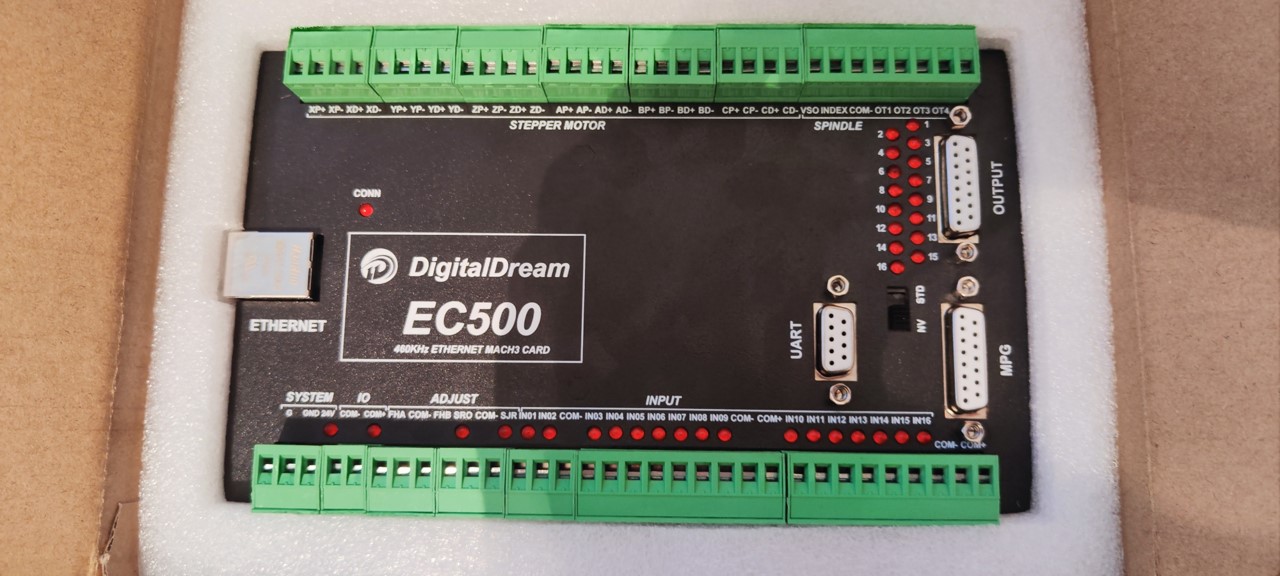
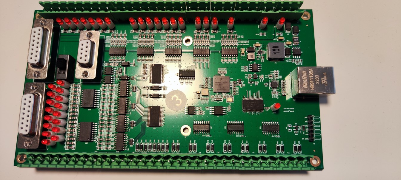
There is now a new EC500 as well. A request for board support was raised on the Remora-EC500 github. It looks so so similar to the EC300 but with some additional inputs.
Attachments:
The following user(s) said Thank You: MX_Master, Murphy
Please Log in or Create an account to join the conversation.
- scotta
-
Topic Author
- Offline
- Platinum Member
-
Less
More
- Posts: 956
- Thank you received: 486
21 Oct 2022 03:49 #254645
by scotta
Replied by scotta on topic Remora - ethernet NVEM / EC300 / EC500 cnc board
After frustrating myself with the J-OB v2 probe and J-Link software, which would successfully read the flash, but nothing I could do would allow erasing and writing the flash... 
So back to MCUXpressoIDE to see if I could get a Flash debug setup working. And finally I have a working tool chain with a cheap and open source CMSIS-DAP probe (ST-Link v2 converted)
It was so nice to be able to load a program into the flash and step through the XiP address space
The LinkServer installed with MCUXpresso can be run from a command line script. This may be the easiest way for people to flash boards, but they will have to install the free MCUXpressoIDE.
I feel much more confident that we'll get Remora running on the RT1052 based boards now!
Now to remove the MCU from the board...
The following user(s) said Thank You: tommylight, MX_Master, Murphy, RogEnk
Please Log in or Create an account to join the conversation.
- MX_Master
-

- Offline
- Premium Member
-

Less
More
- Posts: 92
- Thank you received: 48
21 Oct 2022 13:10 #254678
by MX_Master
Replied by MX_Master on topic Remora - ethernet NVEM / EC300 / EC500 cnc board
Can you provide to people a detailed list how to flash a new firmware with DAP-Link (CMSIS-DAP)?
Please Log in or Create an account to join the conversation.
- scotta
-
Topic Author
- Offline
- Platinum Member
-
Less
More
- Posts: 956
- Thank you received: 486
21 Oct 2022 23:44 #254738
by scotta
Replied by scotta on topic Remora - ethernet NVEM / EC300 / EC500 cnc board
I'll put a working debug program skeleton up on github. A true DAP-link firmware would be the ultimate but at least CMSIS-DAP + MCUExpressoIDE has got us to a working point.Can you provide to people a detailed list how to flash a new firmware with DAP-Link (CMSIS-DAP)?
The following user(s) said Thank You: skench, tommylight, MX_Master, RogEnk
Please Log in or Create an account to join the conversation.
- scotta
-
Topic Author
- Offline
- Platinum Member
-
Less
More
- Posts: 956
- Thank you received: 486
23 Oct 2022 02:54 #254822
by scotta
Replied by scotta on topic Remora - ethernet NVEM / EC300 / EC500 cnc board
There has been a lot or research, trial and error to get to the point where we can program and debug the iMX RT1052 chip on these new Novusun CNC controllers. I've created a repo with a program template that is working with the EC300 controller board, but I see no reason why it wont work with the new NVEM, EC500 etc as the components on these boards appears to be the same.
github.com/scottalford75/iMX_RT1052_QSPI_Flash
This is also an opportunity over the coming posts to document how I got this working as some of the documentation on line does not work!
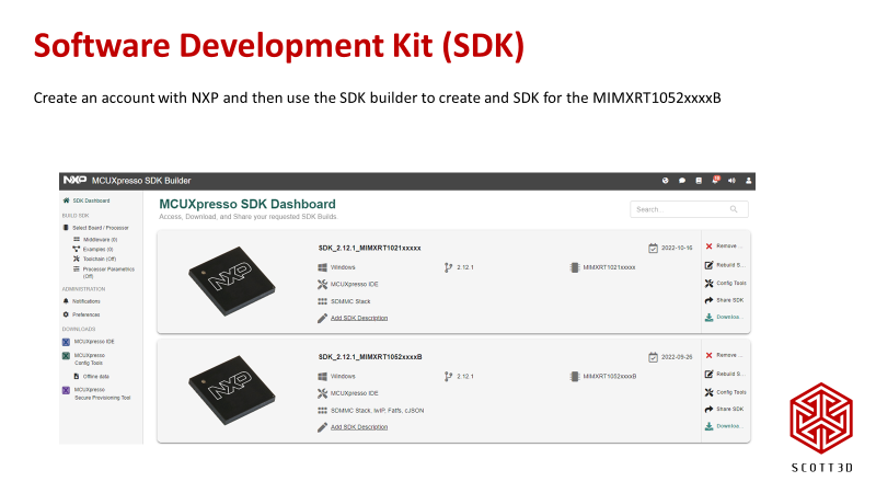
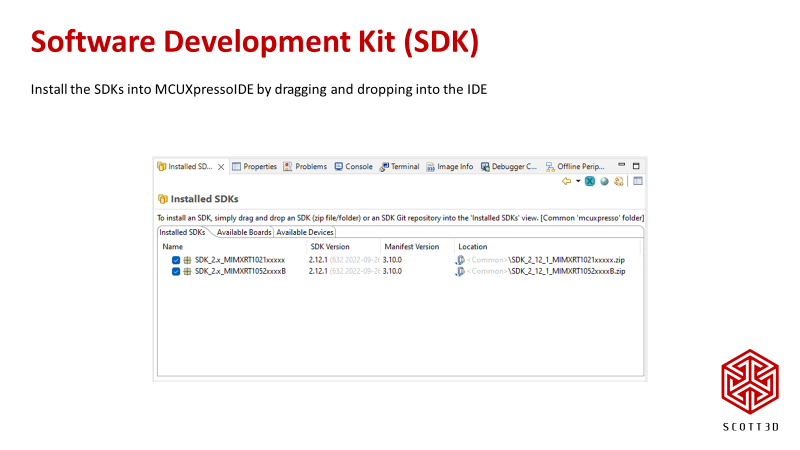
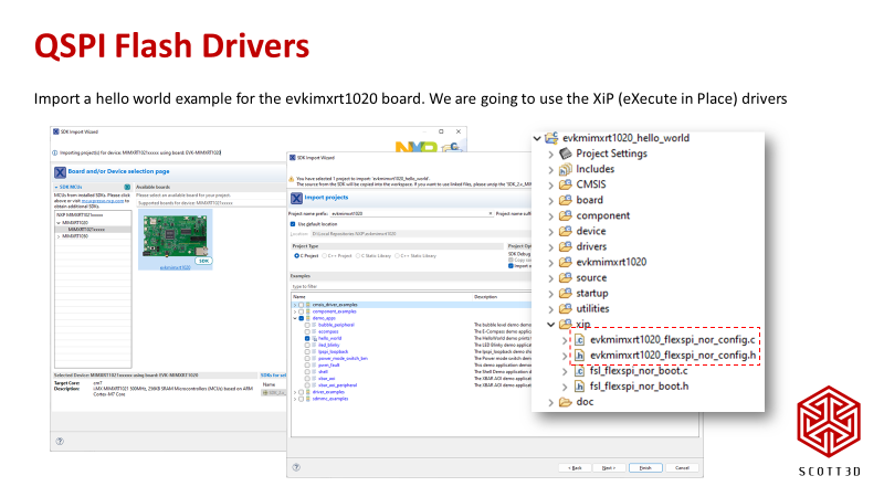
We'll be using MCUXpressoIDE for development and NXP has some tools to create Software Development Kits (SDKs). We'll need two SDK's. One for the RT1052 and another for the RT1021. The EVKMIMXRT1021 development board comes with QSPI flash so we'll take advantage of those drivers.
github.com/scottalford75/iMX_RT1052_QSPI_Flash
This is also an opportunity over the coming posts to document how I got this working as some of the documentation on line does not work!
We'll be using MCUXpressoIDE for development and NXP has some tools to create Software Development Kits (SDKs). We'll need two SDK's. One for the RT1052 and another for the RT1021. The EVKMIMXRT1021 development board comes with QSPI flash so we'll take advantage of those drivers.
Attachments:
The following user(s) said Thank You: tommylight, MX_Master, mrbubble, Murphy, RogEnk
Please Log in or Create an account to join the conversation.
- scotta
-
Topic Author
- Offline
- Platinum Member
-
Less
More
- Posts: 956
- Thank you received: 486
23 Oct 2022 03:07 - 23 Oct 2022 03:12 #254823
by scotta
Replied by scotta on topic Remora - ethernet NVEM / EC300 / EC500 cnc board
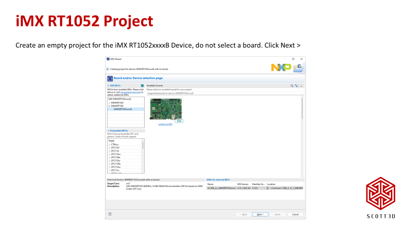
Now to the main game, creating the RT1052 project. Start a New Project and only select the Device, we don't want the overhead of the development board configuration, even though we do get some defaults come through. But we'll fix that.
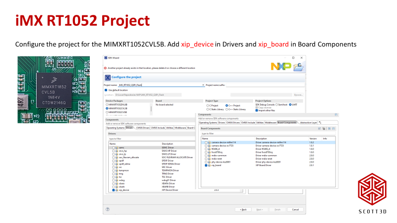
Select the CVL5B package and add both the xip_device and xip_board. This will setup the linker configuration etc for us.
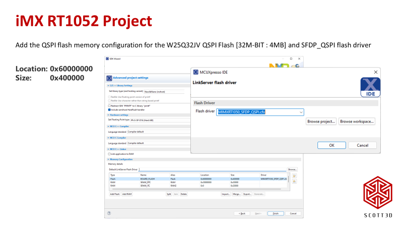
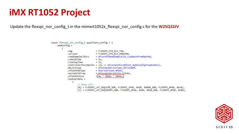
Click next and then configure the Flash. Click on Add Flash and then enter the details for the Winbond W25Q32JV flash. Also select the LinkServer flash driver. Use the MIMXRT1050_SFDP_QSPI driver. This was the key to getting up and going. This driver interrogates the Flash chip and self configures.
Next we will change the flash driver, the one that will be used by the BootROM to load our program, to the one from the RT1021. Delete the files from the xip directory and copy in the ones from the RT1021 and rename them.
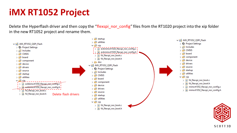
The last step is to correct the flash size. Some documentation says to update some of the LUT settings, but the defaults work and the suggested changes fail, stopping the boot-up.
Select the CVL5B package and add both the xip_device and xip_board. This will setup the linker configuration etc for us.
Click next and then configure the Flash. Click on Add Flash and then enter the details for the Winbond W25Q32JV flash. Also select the LinkServer flash driver. Use the MIMXRT1050_SFDP_QSPI driver. This was the key to getting up and going. This driver interrogates the Flash chip and self configures.
Next we will change the flash driver, the one that will be used by the BootROM to load our program, to the one from the RT1021. Delete the files from the xip directory and copy in the ones from the RT1021 and rename them.
The last step is to correct the flash size. Some documentation says to update some of the LUT settings, but the defaults work and the suggested changes fail, stopping the boot-up.
Attachments:
Last edit: 23 Oct 2022 03:12 by scotta.
The following user(s) said Thank You: MX_Master, mrbubble, RogEnk
Please Log in or Create an account to join the conversation.
- scotta
-
Topic Author
- Offline
- Platinum Member
-
Less
More
- Posts: 956
- Thank you received: 486
23 Oct 2022 03:19 #254824
by scotta
Replied by scotta on topic Remora - ethernet NVEM / EC300 / EC500 cnc board
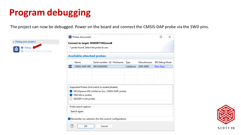
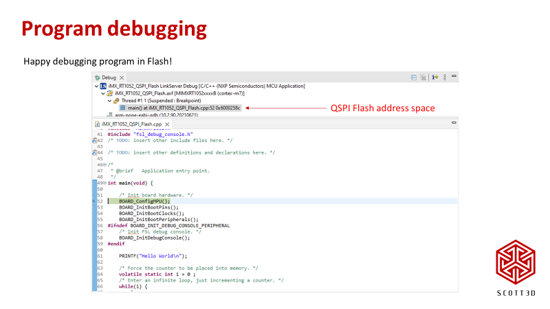
We can now test out debugging. A CMSIS-DAP probe is required and connect only 3 of the SWD pins. On the new NVEM and EC300 there is no 3.3v pin available, so the board needs to be powered.
Clicking on the Debug icon will bring up the Probes selection. Click ok and debug will start.
The LinkServer GUI Flash Tool can be used to run the separate program and erase scripts if needed.
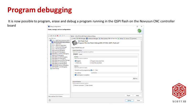
Debugging will download the new program and launch the session. The program should halt at the breakpoint automatically set at main and we should be in the Flash address space of 0x60000000. Now to get programming....
Clicking on the Debug icon will bring up the Probes selection. Click ok and debug will start.
The LinkServer GUI Flash Tool can be used to run the separate program and erase scripts if needed.
Debugging will download the new program and launch the session. The program should halt at the breakpoint automatically set at main and we should be in the Flash address space of 0x60000000. Now to get programming....
Attachments:
The following user(s) said Thank You: skench, tommylight, MX_Master, mrbubble, RogEnk
Please Log in or Create an account to join the conversation.
- Snap1202
- Offline
- New Member
-

Less
More
- Posts: 6
- Thank you received: 2
24 Oct 2022 18:22 #254934
by Snap1202
Replied by Snap1202 on topic Remora - ethernet NVEM / EC300 / EC500 cnc board
Hi all together!
iam more or less new to linux cnc but setup A dozen machines with other systems and happy to work me through Linuxcnc. But i need a little bit of help on configure the machine under remora. I was able to flash the EC500 and Linux is connecting fine.Are there some links maybe,that explain the setup with a non mesa non DB25? If i understand nor the stepconfig or PNCconfig are used under remora. A basic 3 axis limit switch setup is what iam looking for. So if someone has maybe some links or something to start with it would help alot.
Regards Dominik
Please Log in or Create an account to join the conversation.
Time to create page: 0.562 seconds