G Code Generation for Camshaft grinding
- TobiasKa
- Offline
- New Member
-

Less
More
- Posts: 7
- Thank you received: 0
17 Jul 2017 08:57 #95872
by TobiasKa
G Code Generation for Camshaft grinding was created by TobiasKa
Hi Guys,
I recently reworked an old hydraulic grinding machine to be able to grind camshafts for the application within cars.
So I added some servo drives and a mesa-interface card... setting up the HAL and the motor tuning worked pretty fine (so well done... it's a very nice framework).
As the next step I designed a camshaft, which I would like to grind and tried to write some Gcode.
For the Gcode generation I have taken the designed camshaft, which is given in a kind of polar coordinates and interpolated each point with a linear movement.
Very important is that the rotary axis is rotating all the time with the same angular velocity to achieve a smooth surface of the camshaft.
So let's say the target angular velocity of the rotary axis is 0.25RPM.
As the next step I calculated the right velocity of the Z-Axis (the one which is driving the grinding wheel to the camshaft and away).
Therefore I simply used linear velocity and some Protagoras-theorem.
As soon as a tried to run this on the machine, the rotary velocity as everything else than constant.
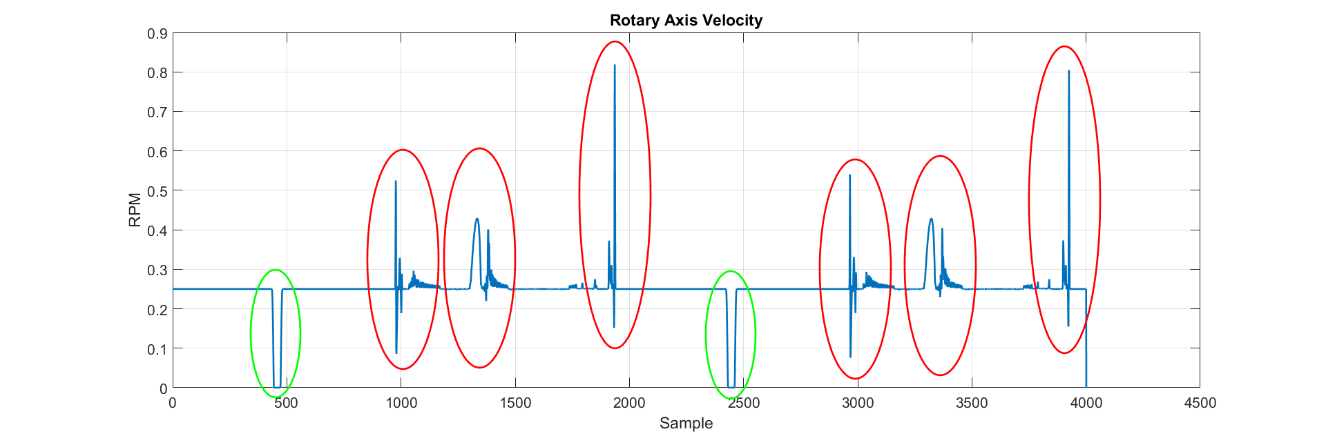
In the above image you can see the setpoint velocity of the rotary axis based on my calculations, measured via the HAL-Scope.
The green deviations are ok for me, because I know why they exists (those are coming from the loop indices calculation).
But the red ones, should not exist.
I'm just wondering if my approach was wrong to the application.
Maybe you can give me any hints, how I can improve this to achieve a constant velocity on the rotary axis
Best Regards
Tobias
I recently reworked an old hydraulic grinding machine to be able to grind camshafts for the application within cars.
So I added some servo drives and a mesa-interface card... setting up the HAL and the motor tuning worked pretty fine (so well done... it's a very nice framework).
As the next step I designed a camshaft, which I would like to grind and tried to write some Gcode.
For the Gcode generation I have taken the designed camshaft, which is given in a kind of polar coordinates and interpolated each point with a linear movement.
Very important is that the rotary axis is rotating all the time with the same angular velocity to achieve a smooth surface of the camshaft.
So let's say the target angular velocity of the rotary axis is 0.25RPM.
As the next step I calculated the right velocity of the Z-Axis (the one which is driving the grinding wheel to the camshaft and away).
Therefore I simply used linear velocity and some Protagoras-theorem.
As soon as a tried to run this on the machine, the rotary velocity as everything else than constant.
In the above image you can see the setpoint velocity of the rotary axis based on my calculations, measured via the HAL-Scope.
The green deviations are ok for me, because I know why they exists (those are coming from the loop indices calculation).
But the red ones, should not exist.
I'm just wondering if my approach was wrong to the application.
Maybe you can give me any hints, how I can improve this to achieve a constant velocity on the rotary axis
Best Regards
Tobias
Please Log in or Create an account to join the conversation.
- TobiasKa
- Offline
- New Member
-
Less
More
- Posts: 7
- Thank you received: 0
17 Jul 2017 08:59 #95873
by TobiasKa
Replied by TobiasKa on topic G Code Generation for Camshaft grinding
Just some additional information:
The attached Files are the first the designed camshaft:
and the G-code file with the calculated velocities at each point
The attached Files are the first the designed camshaft:
and the G-code file with the calculated velocities at each point
Please Log in or Create an account to join the conversation.
- andypugh
-

- Offline
- Moderator
-

Less
More
- Posts: 19876
- Thank you received: 4642
17 Jul 2017 16:16 #95919
by andypugh
Replied by andypugh on topic G Code Generation for Camshaft grinding
I think that this might be a job better handled by slaving the grinding wheel to the angular position, rather than trying to use coordinated motion. This would involve turning the work at a constant speed and using G33 moves.
Furthermore I think that there is a problem with coordinated moves in combined rotary-angular axes. Configuring the machine to use the Y-axis for the rotary position might help with that.
I have experimented with calculating the X position on-the-fly depending on spindle position. I don't think that I yet have all the answers.
Please Log in or Create an account to join the conversation.
- TobiasKa
- Offline
- New Member
-
Less
More
- Posts: 7
- Thank you received: 0
18 Jul 2017 14:48 #95982
by TobiasKa
Replied by TobiasKa on topic G Code Generation for Camshaft grinding
Hi
thank you for your feedback.
So far I defined that two linear axes.
So the machine does not know that the rotary axis is a rotary one.
This have been done, because the rotary should only turn into one direction and I had the fear that the controller or path planner might have the rigorous idea it could reach the desired position faster if it turns into the other direction.
With this approach I have more control over the axis. Furthermore I won't get into the pitfall of any issues of a coordinated movement of a rotary and linear axis.
Is there any documentation existing which describes how a coordinated movement of two axes works under the hood?
So far I used the Linux CNC as a as-is framework.
I did not really had a look into how to manipulate HAL signals and so on.
Therefore I guess, to get a system into a working condition as you had in your linked video, I would need lot of time.
I will try to reconfigure the X axis to a spindle and then work with G33 movements and will post here my update.
Thank you so far
Tobias
Please Log in or Create an account to join the conversation.
- PCW
-

- Offline
- Moderator
-
Less
More
- Posts: 17985
- Thank you received: 5278
18 Jul 2017 15:56 #95986
by PCW
Replied by PCW on topic G Code Generation for Camshaft grinding
Where is the encoder that reads velocity?
If its directly on the rotary axis, the tiniest motion from backlash, servo deadzone,
etc at 0.25 RPM will show huge velocity errors even though the position error may be quite small
that could explain the large (but short) velocity spikes
Also I note that the rotary axis does not appear to be under closed loop speed control
if you look at the worst (longest lasting) speed deviations, there is no matching velocity correction
so these may just be responses of the rotary axis to grinding load changes
Are the sample times in ms? if so the longest lasting velocity error is about 50 ms long and a about 0.2 RPM peak error
this amounts to an accumulated angular error of only about 0.03 degrees...
Please Log in or Create an account to join the conversation.
- TobiasKa
- Offline
- New Member
-
Less
More
- Posts: 7
- Thank you received: 0
24 Jul 2017 10:24 #96341
by TobiasKa
Replied by TobiasKa on topic G Code Generation for Camshaft grinding
Hey PCW
I must admit, my figure from the initial post is not that clear as it could be.
The data you see there is the set-point velocity.
So no actual feedback signal is displayed.
The position error is way less than 100 mdeg.
And the set-point has been recorded without actual grinding anything, so there is no additional external force on the axis.
I tried re-configuring the machine, so that there is a spindle axis in the system and make use of synchronized motion.
But I was not really successful with this. The spindle was somehow not able to hold position and drifted a little bit.
This is not a really good behavior.
Regards
Tobias
Please Log in or Create an account to join the conversation.
- massimodamassa
-
- Offline
- Senior Member
-

Less
More
- Posts: 45
- Thank you received: 9
24 Jul 2017 11:52 #96342
by massimodamassa
Replied by massimodamassa on topic G Code Generation for Camshaft grinding
I would set the spindle axis as axis A and the axis of the grinding wheel as axis Y
Please Log in or Create an account to join the conversation.
- TobiasKa
- Offline
- New Member
-
Less
More
- Posts: 7
- Thank you received: 0
24 Jul 2017 12:25 #96344
by TobiasKa
Replied by TobiasKa on topic G Code Generation for Camshaft grinding
Well at the end it is not that important which axis name I give the individual axis
whether I call it A, X or Y.
The G33 can only synchronize movements between a spindle (S) and any other axis.
But a spindle has some limitations (e.g. move to position and hold), so the G33 does not really work
whether I call it A, X or Y.
The G33 can only synchronize movements between a spindle (S) and any other axis.
But a spindle has some limitations (e.g. move to position and hold), so the G33 does not really work
Please Log in or Create an account to join the conversation.
- andypugh
-
- Offline
- Moderator
-
Less
More
- Posts: 19876
- Thank you received: 4642
26 Jul 2017 16:17 #96487
by andypugh
Replied by andypugh on topic G Code Generation for Camshaft grinding
I think that coordinated moves in angular and linear axes is probably the way to go, and you probably do want to configure the rotary axis as the Y, as this should allow the trajectory planner to blend it.
Which version of LinuxCNC are you using? 2.7 should bland the moves rather better than the previous versions.
Which version of LinuxCNC are you using? 2.7 should bland the moves rather better than the previous versions.
Please Log in or Create an account to join the conversation.
- TobiasKa
- Offline
- New Member
-
Less
More
- Posts: 7
- Thank you received: 0
27 Jul 2017 05:33 #96535
by TobiasKa
Replied by TobiasKa on topic G Code Generation for Camshaft grinding
Hi,
Currently I'm using 2.7.9. I updated recently from 2.7.5.
With this update I did not notice any increase in performance.
Currently I'm configured two linear axes. Do you expect any better performance if the rotary axis is configured as a rotary axis?
Currently I'm using 2.7.9. I updated recently from 2.7.5.
With this update I did not notice any increase in performance.
Currently I'm configured two linear axes. Do you expect any better performance if the rotary axis is configured as a rotary axis?
Please Log in or Create an account to join the conversation.
Time to create page: 0.113 seconds