Linear Encoder, PID and Backlash
- helioz2000
- Offline
- New Member
-

Less
More
- Posts: 16
- Thank you received: 8
06 May 2020 12:33 #166870
by helioz2000
Linear Encoder, PID and Backlash was created by helioz2000
I'm integrating encoders into and existing linuxCNC mill with stepper motors.
The BACKLASH setting (0.4mm) has been carefully tuned to give reliable positioning without encoder use.
Now I'm modifying the system to use a linear encoder and PID.
The linear encoder is measuring table travel.
Everything is functioning as expected and I'm in the process of tuning the PID controller.
My questions are prompted by this observation:
With a high P-term, on every direction change I get a big oscillation on PID output which takes a fews of cycles to settle.
This oscillation only occurs on change of direction.
I fully understand why the PID controller produces a high output/overshoot during the backlash take-up period as the motor is speeding up but velocity feedback stays at zero.
My question relates to the interaction between PID and BACKLASH:
What part (if any) does BACKLASH play when using a PID controller (with velocity command output)?
Should the BACKLASH setting be set to 0 when using a PID controller?
Is it possible to "limit" the pid output during the backlash take-up period?
What is considered "best practice" in this scenario?
Thanks for looking at my question.
Please Log in or Create an account to join the conversation.
- tommylight
-

- Away
- Moderator
-

Less
More
- Posts: 21594
- Thank you received: 7374
06 May 2020 13:10 #166871
by tommylight
Replied by tommylight on topic Linear Encoder, PID and Backlash
I do not think using scales and backlash together is the way to, can you test with no backlash set at all ?
Please Log in or Create an account to join the conversation.
- helioz2000
- Offline
- New Member
-
Less
More
- Posts: 16
- Thank you received: 8
09 May 2020 08:30 - 09 May 2020 08:32 #167126
by helioz2000
Replied by helioz2000 on topic Linear Encoder, PID and Backlash
Thanks tommylight, I have everything configured and it is working but I'm not 100% satisfied, even with BACKLASH=0.
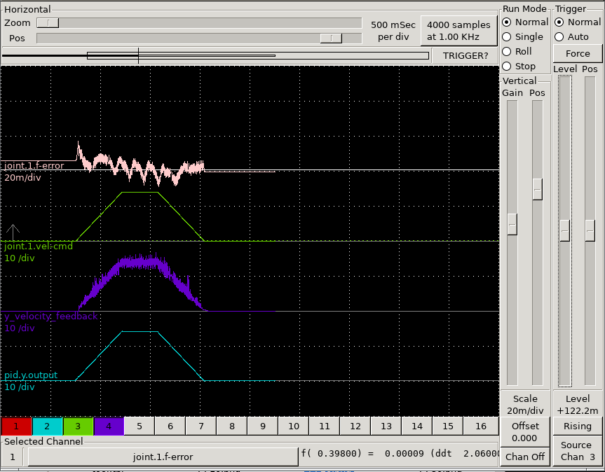
Without direction change the position feedback follows the velocity command very closely.
On a direction change the backlash causes the PID to do this:
The purple trace (velocity feedback) clearly shows the delay between the motor starting to turn (i.e. green trace) and (after backlash) the table finally starting to move.
I realise the solution to the problem is to use ball screws (on order) but I was wondering if there is any way to overcome the pid-backlash problem?
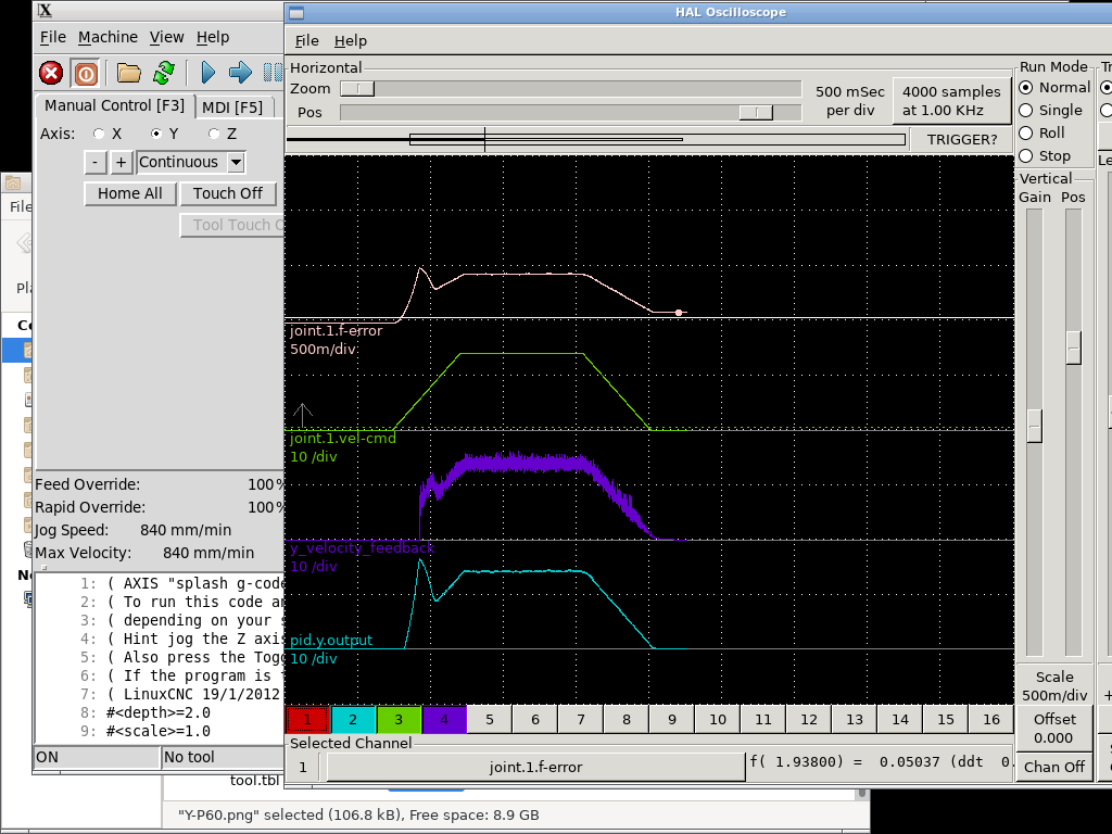
To complete the picture, here is the same trace but without direction change:
Note: Following error trace is on high zoom level.
Without direction change the position feedback follows the velocity command very closely.
On a direction change the backlash causes the PID to do this:
The purple trace (velocity feedback) clearly shows the delay between the motor starting to turn (i.e. green trace) and (after backlash) the table finally starting to move.
I realise the solution to the problem is to use ball screws (on order) but I was wondering if there is any way to overcome the pid-backlash problem?
To complete the picture, here is the same trace but without direction change:
Note: Following error trace is on high zoom level.
Attachments:
Last edit: 09 May 2020 08:32 by helioz2000.
Please Log in or Create an account to join the conversation.
- tommylight
-
- Away
- Moderator
-
Less
More
- Posts: 21594
- Thank you received: 7374
09 May 2020 09:19 #167130
by tommylight
Replied by tommylight on topic Linear Encoder, PID and Backlash
Omit the backlash line in ini file
#backlash=0
#backlash=0
Please Log in or Create an account to join the conversation.
- bbsr_5a
- Offline
- Platinum Member
-

Less
More
- Posts: 544
- Thank you received: 106
09 May 2020 09:35 #167131
by bbsr_5a
Replied by bbsr_5a on topic Linear Encoder, PID and Backlash
why is there a horrible jitter in the feedback
isent the cable shielded
and or the connectors gronded
isent the cable shielded
and or the connectors gronded
Please Log in or Create an account to join the conversation.
- chris@cnc
- Offline
- Platinum Member
-
Less
More
- Posts: 529
- Thank you received: 140
09 May 2020 09:46 #167134
by chris@cnc
Replied by chris@cnc on topic Linear Encoder, PID and Backlash
Hi, the combination of backlash and scale is difficult. On real cnc machines there are parameters around the backlash control loop. But the first rule is: before the parameters are tuned, the mechanics must be 100% okay. And 4/10 backlash is far from a good machanic. I also have a rack as a drive with a similar backlash and scale but with servo motors. they can be resolved higher and regulate more precisely with a small PID. To do this, the rack and gear must also be 100% parallel. my mechanics are also not perfectly aligned and each axis plays differently even though the parameters are the same. But when I mill a circle it is round to 0.1mm and that's okay for me.
A smaller pitch could improve your problem. So you would have more pulses for the control loop. And there is a lot of noise on your scale feedack. Vibrations or something wrong with the cable.
A smaller pitch could improve your problem. So you would have more pulses for the control loop. And there is a lot of noise on your scale feedack. Vibrations or something wrong with the cable.
Please Log in or Create an account to join the conversation.
- helioz2000
- Offline
- New Member
-
Less
More
- Posts: 16
- Thank you received: 8
10 May 2020 10:07 #167246
by helioz2000
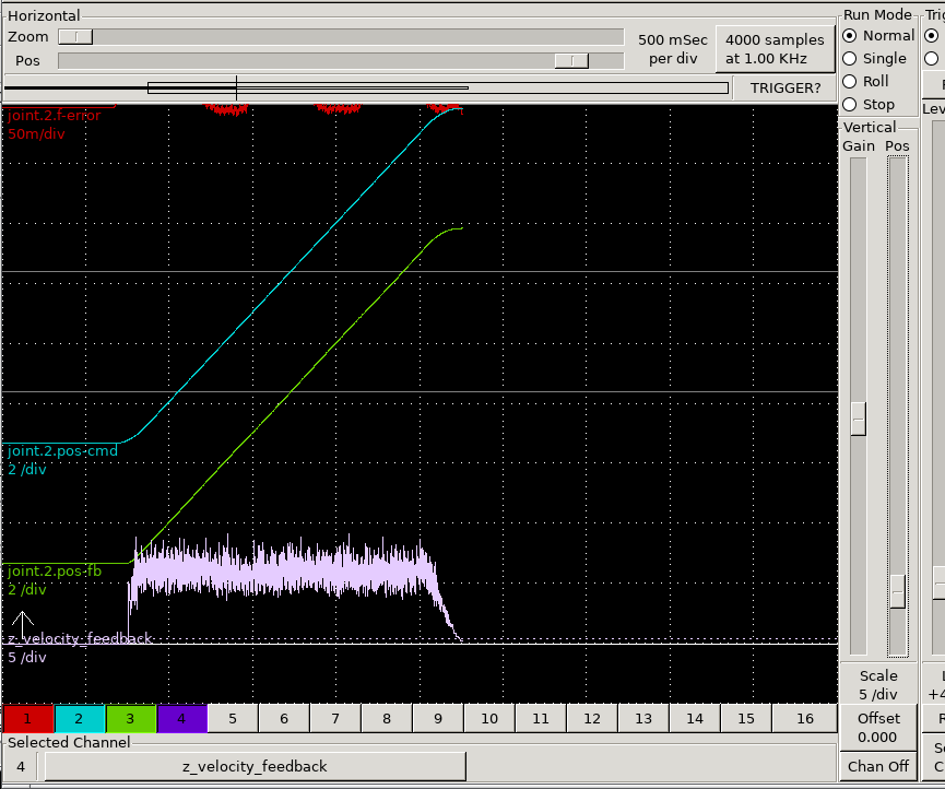
As you can see, the position signal is perfect whereas the velocity signal is noisy, so I conclude the noise is coming from the calculation.
I suspect the noise on the velocity signal is a combination of using a 5um resolution encoder on a low quality [Chinese] ACME lead screw. At the maximum speed of 14mm/sec the encoder signal produces only 2800 pulses per second, that's one pulse every 357us.
I'm not sure how often the velocity calc is performed, but, the low resolution encoder will produce very few pulses for a fast measuring system and therefore a 1 digit variation (as is usual in all digital measurement) is of significant magnitude and shows up as "noise" on the trace.
The encoder cable is shielded all the way to the Mesa 7i85S card and the shield is grounded on the Mesa card end.
Replied by helioz2000 on topic Linear Encoder, PID and Backlash
You have to remember the velocity feedback is coming from a linear encoder attached to the table, not the motor. The encoder provides pulses, not an analog speed signal like a tacho. As the velocity signal is calculated from the pulses the "noise" or jitter is unlikely to come from interference. If there was any interference generating additional pulses it would also have to affect the position feedback. Here is a trace of the position signal together with the velocity:why is there a horrible jitter in the feedback
isn't the cable shielded
and or the connectors grounded
As you can see, the position signal is perfect whereas the velocity signal is noisy, so I conclude the noise is coming from the calculation.
I suspect the noise on the velocity signal is a combination of using a 5um resolution encoder on a low quality [Chinese] ACME lead screw. At the maximum speed of 14mm/sec the encoder signal produces only 2800 pulses per second, that's one pulse every 357us.
I'm not sure how often the velocity calc is performed, but, the low resolution encoder will produce very few pulses for a fast measuring system and therefore a 1 digit variation (as is usual in all digital measurement) is of significant magnitude and shows up as "noise" on the trace.
The encoder cable is shielded all the way to the Mesa 7i85S card and the shield is grounded on the Mesa card end.
Attachments:
The following user(s) said Thank You: OT-CNC
Please Log in or Create an account to join the conversation.
- PCW
-

- Offline
- Moderator
-
Less
More
- Posts: 17905
- Thank you received: 5243
10 May 2020 11:21 - 10 May 2020 11:25 #167253
by PCW
Replied by PCW on topic Linear Encoder, PID and Backlash
Noise on hm2 encoder velocity signals at a constant speed is more likely caused
by actual motion variation and quadrature errors ( lack of perfect 90 degree offset between A and B )
than calculation. Velocity estimation is done by a delta_counts/deltaT calculation where deltaT is not the sample
period but rather the time between count changes. This eliminates the count sample time uncertainty in
velocity estimation but is still susceptible to quadrature errors. Sometimes you can improve
the quadrature accuracy by mechanical or electrical encoder adjustments.
Last edit: 10 May 2020 11:25 by PCW. Reason: eliminate smiley/clarify
The following user(s) said Thank You: helioz2000
Please Log in or Create an account to join the conversation.
- helioz2000
- Offline
- New Member
-
Less
More
- Posts: 16
- Thank you received: 8
13 May 2020 10:33 #167639
by helioz2000
My first suspicion is motion variation on the cheap Chinese made ACME screws as I have observed up to 80u variation in the lead screw pitch.
The linear encoders are no-brand cheapies, so quadrature errors are certainly possible.
The "noisy" velocity signal does not appear to be causing any problems as far as I can see so I'll leave it as is.
However, I will re-evaluate once I have fitted ball screws.
Replied by helioz2000 on topic Linear Encoder, PID and Backlash
Many thanks for your authoritative answer.Noise on hm2 encoder velocity signals at a constant speed is more likely caused
by actual motion variation and quadrature errors ( lack of perfect 90 degree offset between A and B )
than calculation.
My first suspicion is motion variation on the cheap Chinese made ACME screws as I have observed up to 80u variation in the lead screw pitch.
The linear encoders are no-brand cheapies, so quadrature errors are certainly possible.
The "noisy" velocity signal does not appear to be causing any problems as far as I can see so I'll leave it as is.
However, I will re-evaluate once I have fitted ball screws.
Please Log in or Create an account to join the conversation.
- Henk
- Offline
- Platinum Member
-
Less
More
- Posts: 408
- Thank you received: 92
13 May 2020 20:08 #167676
by Henk
Replied by Henk on topic Linear Encoder, PID and Backlash
For what it's worth....
In my experience ( 9 different machines), there is no substitute for good mechanical components and near zero backlash.
In my experience ( 9 different machines), there is no substitute for good mechanical components and near zero backlash.
The following user(s) said Thank You: helioz2000
Please Log in or Create an account to join the conversation.
Time to create page: 4.642 seconds