2 pole 6 Position rotary switch for (2x) MPG enable and scale settings
- denhen89
-
 Topic Author
- Offline
- Elite Member
-

Less
More
- Posts: 301
- Thank you received: 27
30 May 2020 08:36 #169395
by denhen89
2 pole 6 Position rotary switch for (2x) MPG enable and scale settings was created by denhen89
Hello guys,
after i got the both MPGs to work properly, as well as some buttons like Start/Step and Pause/Resume, a potentiometer for controlling Feed and for my Lathe project i am currently stuck with the Scale selector switch. (2 Pole, 6 position: Aliexpress link ).
I have used the exacty same .hal settings as "Rodw" did in his Rods "Spaceship" Scratch built Plasma Cutter buildPlasma build
*I have changed "or2.3" to "or2.1", because i currently have only 2x or2
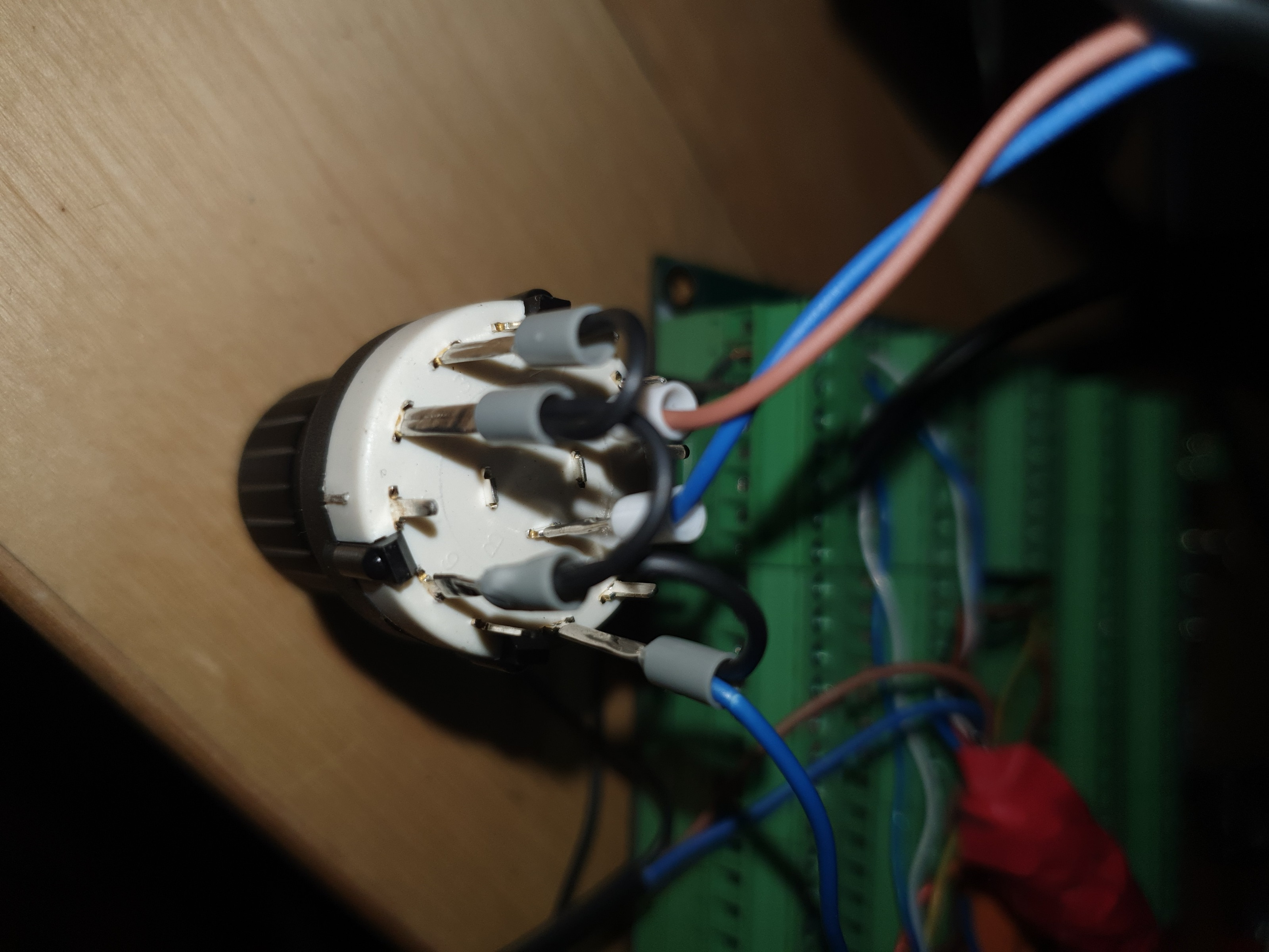
I connected PIN 3, 4, 6 and 8 together with one wire (please take a look at the picture) and connected PIN 8 to +24V, so all have +24V.
The A and B pin to input 21 and 22 on my Mesa 7i76E.
So, i think its exactly as Rodw did.
I have opened Halmeter, choosed pin "mux4.0.out" which shows "0" when the switch is turned completly to the left side, when moved one click to the right it shows "0,1mm", then next clicks always "0".
I dont understand why, i really tried to find the problem. For example i choosed other pins instead e.g. pin 6 and 8, but what i ones got was that i got 2 times 0.1mm, so i seems like its some kind of .hal config problem.
When i exchange the Pins in the below 2 lines (.input 21 will be on top, 22 on bottom), i get 1,00mm instead of 0.1mm, but all other show "0" on Halmeter.
net mux-in1 or2.3.in0 <= hm2_7i76e.0.7i76.0.0.input-22 => mux4.0.sel0
net mux-in2 or2.3.in1 <= hm2_7i76e.0.7i76.0.0.input-21 => mux4.0.sel1
When i play around with the position pins then i get e.g. (switch rotated from left to right/clockwise):
Position 1 : "0"
Position 2 : "1,00 mm"
Position 3 : "0"
Position 4 : "1,00 mm"
No matter how i change the pins i do get no other value than "0" or "1,00mm" (or 0,10 mm, when exchanging the input Pins)
I have replied to Rodw and he wrote that my Rotary switch might be not same as his, so i have to create a Truth table and check which pins are on/off on the 4 positions i need. I have tried to get some informations how to do that on youtube and google and i am pretty sure i understand it correctly and i have of course already tryed the wiring setup i thought its correct, but i still get no other Values than "0" and "1,00 mm".
Here are the table to show which pins are ON when on all 6 positions:
Position 1: A - 1 / B - 7
Position 2: A - 2 / B - 8
Position 3: A - 3 / B - 9
Position 4: A - 4 / B - 10
Position 5: A - 5 / B - 11
Position 6: A - 6 / B - 12
So, e.g. in Position 1, the Pole "A" is connected with "Pin 1" and Pole "B" with "Pin 7".
The Truth table should be as Rodw posted:
00
01
10
11
If i understand it correctly, in Position 1, Pole A and Pole B should be both on "false", so that the result is "00"
On Position 2, Pole A should be "false" and Pole B "true".
Position 3: Pole A should be "true" and Pole B "false"
Position 4: Pole A and B both "true".
If thats correct, then i should wire up those terminal Pins together and then to +24V: 3,4,8 & 10.
Short explation of my thinking :
:
When the switch is in Position 1, A1 and B7 should not get +24V, to get "00"
When the switch is in Position 2, A2 should not get +24V, but B8 should get +24V, to get "01"
When the switch is in Position 3: A3 should get +24V, but B9 should not get +24V, to get "10"
When the switch is in Position 4: A4 and B10 should get both +24V to get "11"
My explenation might be wrong and difficult to understand, but if so, please ignore it.
With this wiring setup i get this values on Halmeter Pin "mux4.0.out":
Position 1: 0
Position 2: 1 (1,00 mm)
Position 3: 0
Position 4: 1 (1,00 mm)
I somehow do not believe that my thinking is correct, just because its not working as it should, but also i somehow think that the .hal setup is not correct, because i am getting values on Halmeter, but not the correct one.
I checked also those pins "mux4.0.sel0" and "mux4.0.sel1" and found out that sel1 is always "FALSE"
Also i checked pins "or2.1.in0" and "or2.1.in1" and found out that .in1 is always "FALSE.
Thats the reason i am thinking that the hal setup is wrong, but it works for Rodw, so i am currently a bit confused.
Even if everything is wrong what i did, at least you see that i did try to get it done by my self.
I hope you can help me out. I have attached my mpg.HAL and my main .HAL.
Thanks in advance.
after i got the both MPGs to work properly, as well as some buttons like Start/Step and Pause/Resume, a potentiometer for controlling Feed and for my Lathe project i am currently stuck with the Scale selector switch. (2 Pole, 6 position: Aliexpress link ).
I have used the exacty same .hal settings as "Rodw" did in his Rods "Spaceship" Scratch built Plasma Cutter buildPlasma build
# Metric units used
loadrt hm2_eth board_ip="10.10.10.10" config="firmware=hm2/7i76/7i76e.BIT num_encoders=1 num_pwmgens=0 num_stepgens=5  sserial_port_0=2xxxx"

loadrt mux4 count=1
addf mux4.0 servo-thread
loadrt or2 count=4
addf or2.3  servo-thread

setp axis.x.jog-vel-mode 0
net x-jog-counter <=  hm2_7i76e.0.7i76.0.0.enc0.count
net x-jog-counter => axis.x.jog-counts
net mux-in1 or2.3.in0 <= hm2_7i76e.0.7i76.0.0.input-22 => mux4.0.sel0
net mux-in2 or2.3.in1 <= hm2_7i76e.0.7i76.0.0.input-21 => mux4.0.sel1
net x-jog-enable <= or2.3.out
net x-jog-enable => axis.x.jog-enable
setp mux4.0.in0 0.0
setp mux4.0.in1 1.0
setp mux4.0.in2 0.1
setp mux4.0.in3 0.01
net x-jog-scale mux4.0.out => axis.x.jog-scale
*I have changed "or2.3" to "or2.1", because i currently have only 2x or2
I connected PIN 3, 4, 6 and 8 together with one wire (please take a look at the picture) and connected PIN 8 to +24V, so all have +24V.
The A and B pin to input 21 and 22 on my Mesa 7i76E.
So, i think its exactly as Rodw did.
I have opened Halmeter, choosed pin "mux4.0.out" which shows "0" when the switch is turned completly to the left side, when moved one click to the right it shows "0,1mm", then next clicks always "0".
I dont understand why, i really tried to find the problem. For example i choosed other pins instead e.g. pin 6 and 8, but what i ones got was that i got 2 times 0.1mm, so i seems like its some kind of .hal config problem.
When i exchange the Pins in the below 2 lines (.input 21 will be on top, 22 on bottom), i get 1,00mm instead of 0.1mm, but all other show "0" on Halmeter.
net mux-in1 or2.3.in0 <= hm2_7i76e.0.7i76.0.0.input-22 => mux4.0.sel0
net mux-in2 or2.3.in1 <= hm2_7i76e.0.7i76.0.0.input-21 => mux4.0.sel1
When i play around with the position pins then i get e.g. (switch rotated from left to right/clockwise):
Position 1 : "0"
Position 2 : "1,00 mm"
Position 3 : "0"
Position 4 : "1,00 mm"
No matter how i change the pins i do get no other value than "0" or "1,00mm" (or 0,10 mm, when exchanging the input Pins)
I have replied to Rodw and he wrote that my Rotary switch might be not same as his, so i have to create a Truth table and check which pins are on/off on the 4 positions i need. I have tried to get some informations how to do that on youtube and google and i am pretty sure i understand it correctly and i have of course already tryed the wiring setup i thought its correct, but i still get no other Values than "0" and "1,00 mm".
Here are the table to show which pins are ON when on all 6 positions:
Position 1: A - 1 / B - 7
Position 2: A - 2 / B - 8
Position 3: A - 3 / B - 9
Position 4: A - 4 / B - 10
Position 5: A - 5 / B - 11
Position 6: A - 6 / B - 12
So, e.g. in Position 1, the Pole "A" is connected with "Pin 1" and Pole "B" with "Pin 7".
The Truth table should be as Rodw posted:
00
01
10
11
If i understand it correctly, in Position 1, Pole A and Pole B should be both on "false", so that the result is "00"
On Position 2, Pole A should be "false" and Pole B "true".
Position 3: Pole A should be "true" and Pole B "false"
Position 4: Pole A and B both "true".
If thats correct, then i should wire up those terminal Pins together and then to +24V: 3,4,8 & 10.
Short explation of my thinking
:When the switch is in Position 1, A1 and B7 should not get +24V, to get "00"
When the switch is in Position 2, A2 should not get +24V, but B8 should get +24V, to get "01"
When the switch is in Position 3: A3 should get +24V, but B9 should not get +24V, to get "10"
When the switch is in Position 4: A4 and B10 should get both +24V to get "11"
My explenation might be wrong and difficult to understand, but if so, please ignore it.
With this wiring setup i get this values on Halmeter Pin "mux4.0.out":
Position 1: 0
Position 2: 1 (1,00 mm)
Position 3: 0
Position 4: 1 (1,00 mm)
I somehow do not believe that my thinking is correct, just because its not working as it should, but also i somehow think that the .hal setup is not correct, because i am getting values on Halmeter, but not the correct one.
I checked also those pins "mux4.0.sel0" and "mux4.0.sel1" and found out that sel1 is always "FALSE"
Also i checked pins "or2.1.in0" and "or2.1.in1" and found out that .in1 is always "FALSE.
Thats the reason i am thinking that the hal setup is wrong, but it works for Rodw, so i am currently a bit confused.
Even if everything is wrong what i did, at least you see that i did try to get it done by my self.
I hope you can help me out. I have attached my mpg.HAL and my main .HAL.
Thanks in advance.
Please Log in or Create an account to join the conversation.
- tommylight
-

- Away
- Moderator
-

Less
More
- Posts: 21533
- Thank you received: 7340
30 May 2020 09:54 #169403
by tommylight
Replied by tommylight on topic 2 pole 6 Position rotary switch for (2x) MPG enable and scale settings
We need to see the inner workings of that switch, otherwise it is a guessing game.
Please Log in or Create an account to join the conversation.
- denhen89
-
Topic Author
- Offline
- Elite Member
-
Less
More
- Posts: 301
- Thank you received: 27
30 May 2020 09:55 #169404
by denhen89
Replied by denhen89 on topic 2 pole 6 Position rotary switch for (2x) MPG enable and scale settings
i opened it on yesterday, but i will do it now again and post a picture
The following user(s) said Thank You: tommylight
Please Log in or Create an account to join the conversation.
- denhen89
-
Topic Author
- Offline
- Elite Member
-
Less
More
- Posts: 301
- Thank you received: 27
30 May 2020 10:07 #169409
by denhen89
Replied by denhen89 on topic 2 pole 6 Position rotary switch for (2x) MPG enable and scale settings
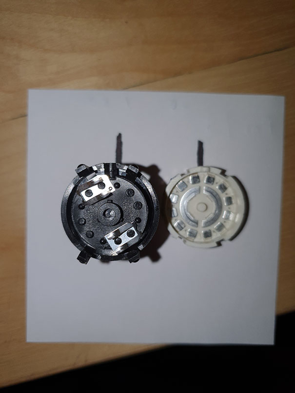
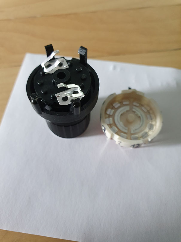
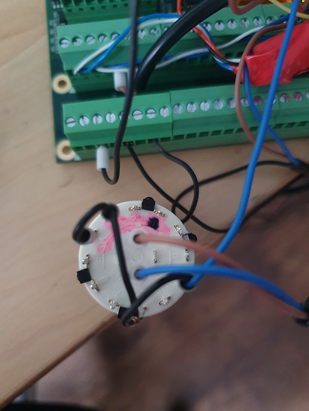
Please take a look at the 3 pictures which shows the inner workings and on the third picture you see that wiring setup i had before.
(i marked with the black marker the position how the both parts fit together)
I hope those pictures help.
(i marked with the black marker the position how the both parts fit together)
I hope those pictures help.
Attachments:
Please Log in or Create an account to join the conversation.
- tommylight
-
- Away
- Moderator
-
Less
More
- Posts: 21533
- Thank you received: 7340
30 May 2020 11:03 #169412
by tommylight
Replied by tommylight on topic 2 pole 6 Position rotary switch for (2x) MPG enable and scale settings
That seems OK from what i can gather, now the black jumped wire should go to +24V and the two middle ones to inputs.
If the above is correct, check the inputs as one of them might not be where the HAL expects it.
If the above is correct, check the inputs as one of them might not be where the HAL expects it.
Please Log in or Create an account to join the conversation.
- denhen89
-
Topic Author
- Offline
- Elite Member
-
Less
More
- Posts: 301
- Thank you received: 27
30 May 2020 11:30 - 30 May 2020 11:30 #169415
by denhen89
Replied by denhen89 on topic 2 pole 6 Position rotary switch for (2x) MPG enable and scale settings
Its working!
Thanks a lot for letting me know that my wiring setup was correct and i should check the inputs.
I am not sure why it has not worked, because the outputs ( A and B ) where wired to the correct input terminals 21 and 22.
What i now did: I took them out of input 21 and 22 and put them in to input 8 and 9 and of course changed in my .hal the inputs to 8 and 9.
I opened Linuxcnc and the switch worked, but the scale order was a bit wrong:
Pos 1: 0
Pos 2: 0.1
Pos 3: 1.00 mm
Pos 4: 0.01 mm
So, i changed in the hal the order of the "setp mux4.0.in" lines and now the order is correct.
Thank you very much tommylight!
I am also very happy, because my thinking was correct when trying to get it done without help, but i just wasnt sure because it has not worked properly.
I learned something and got the motivation to learn more.
I wish you and all others a nice weekend")
Thanks a lot for letting me know that my wiring setup was correct and i should check the inputs.
I am not sure why it has not worked, because the outputs ( A and B ) where wired to the correct input terminals 21 and 22.
What i now did: I took them out of input 21 and 22 and put them in to input 8 and 9 and of course changed in my .hal the inputs to 8 and 9.
I opened Linuxcnc and the switch worked, but the scale order was a bit wrong:
Pos 1: 0
Pos 2: 0.1
Pos 3: 1.00 mm
Pos 4: 0.01 mm
So, i changed in the hal the order of the "setp mux4.0.in" lines and now the order is correct.
Thank you very much tommylight!
I am also very happy, because my thinking was correct when trying to get it done without help, but i just wasnt sure because it has not worked properly.
I learned something and got the motivation to learn more.
I wish you and all others a nice weekend
Last edit: 30 May 2020 11:30 by denhen89.
The following user(s) said Thank You: tommylight, Clive S
Please Log in or Create an account to join the conversation.
- tommylight
-
- Away
- Moderator
-
Less
More
- Posts: 21533
- Thank you received: 7340
30 May 2020 12:05 #169416
by tommylight
Replied by tommylight on topic 2 pole 6 Position rotary switch for (2x) MPG enable and scale settings
Nice.
One thing to keep in mind when wiring Mesa and other boards, inputs and outputs start from 0, so input 1 on connector is input 0 in hal, and so on.
One thing to keep in mind when wiring Mesa and other boards, inputs and outputs start from 0, so input 1 on connector is input 0 in hal, and so on.
Please Log in or Create an account to join the conversation.
- denhen89
-
Topic Author
- Offline
- Elite Member
-
Less
More
- Posts: 301
- Thank you received: 27
30 May 2020 12:25 - 30 May 2020 12:39 #169418
by denhen89
Replied by denhen89 on topic 2 pole 6 Position rotary switch for (2x) MPG enable and scale settings
You are right.
I was something i knew earlier because i ones had this problem already, but please look at this picture from grabcad of the 7i76E on bottom (The inputs seem to be wrong, but when counting from the input 16 from TB6 and continue terminal TB5 to pin 22 then it seems to be the correct inputs)
Because of that picture i choosed Input 21 and 22. I am now a bit angry about my self, because i thought about it to change in the .hal to input 20 and 21 before i wrote the thread, but i dont know why i have not done it.. I could save your and my time, because that was the only reason why the switch/settings did not work properly.
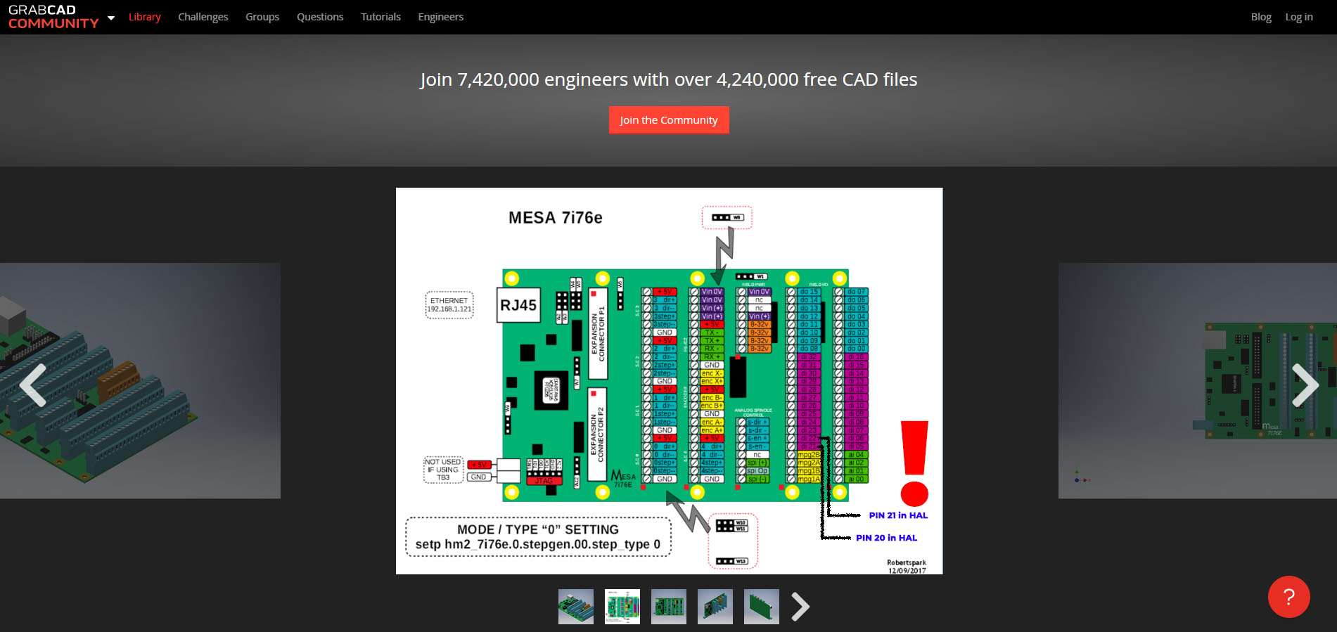
EDIT: i edited the picture and marked the correct Pin names for the .HAL. This might help others in future so that they not get confused by the original picture which was not edited.
I was something i knew earlier because i ones had this problem already, but please look at this picture from grabcad of the 7i76E on bottom (The inputs seem to be wrong, but when counting from the input 16 from TB6 and continue terminal TB5 to pin 22 then it seems to be the correct inputs)
Because of that picture i choosed Input 21 and 22. I am now a bit angry about my self, because i thought about it to change in the .hal to input 20 and 21 before i wrote the thread, but i dont know why i have not done it.. I could save your and my time, because that was the only reason why the switch/settings did not work properly.
EDIT: i edited the picture and marked the correct Pin names for the .HAL. This might help others in future so that they not get confused by the original picture which was not edited.
Attachments:
Last edit: 30 May 2020 12:39 by denhen89.
Please Log in or Create an account to join the conversation.
- tommylight
-
- Away
- Moderator
-
Less
More
- Posts: 21533
- Thank you received: 7340
30 May 2020 12:27 #169419
by tommylight
Replied by tommylight on topic 2 pole 6 Position rotary switch for (2x) MPG enable and scale settings
Picture ?
Please Log in or Create an account to join the conversation.
- denhen89
-
Topic Author
- Offline
- Elite Member
-
Less
More
- Posts: 301
- Thank you received: 27
30 May 2020 12:35 - 30 May 2020 12:42 #169420
by denhen89
Replied by denhen89 on topic 2 pole 6 Position rotary switch for (2x) MPG enable and scale settings
Sorry, now it is there.
I have edited the picture in Photoshop so thats it clear. The original picture is from Grabcad, here the link: grabcad.com/library/mesa-7i76e-7i76e-1
EDIT: i just thought about it if the reason for the wrong input pin numbers is because i have it in Serial mode 2 ?
In the standard mode the Pins 21 and 22 might be correct as on the grabcad picture.
Last edit: 30 May 2020 12:42 by denhen89.
Please Log in or Create an account to join the conversation.
Time to create page: 0.199 seconds