Hello,
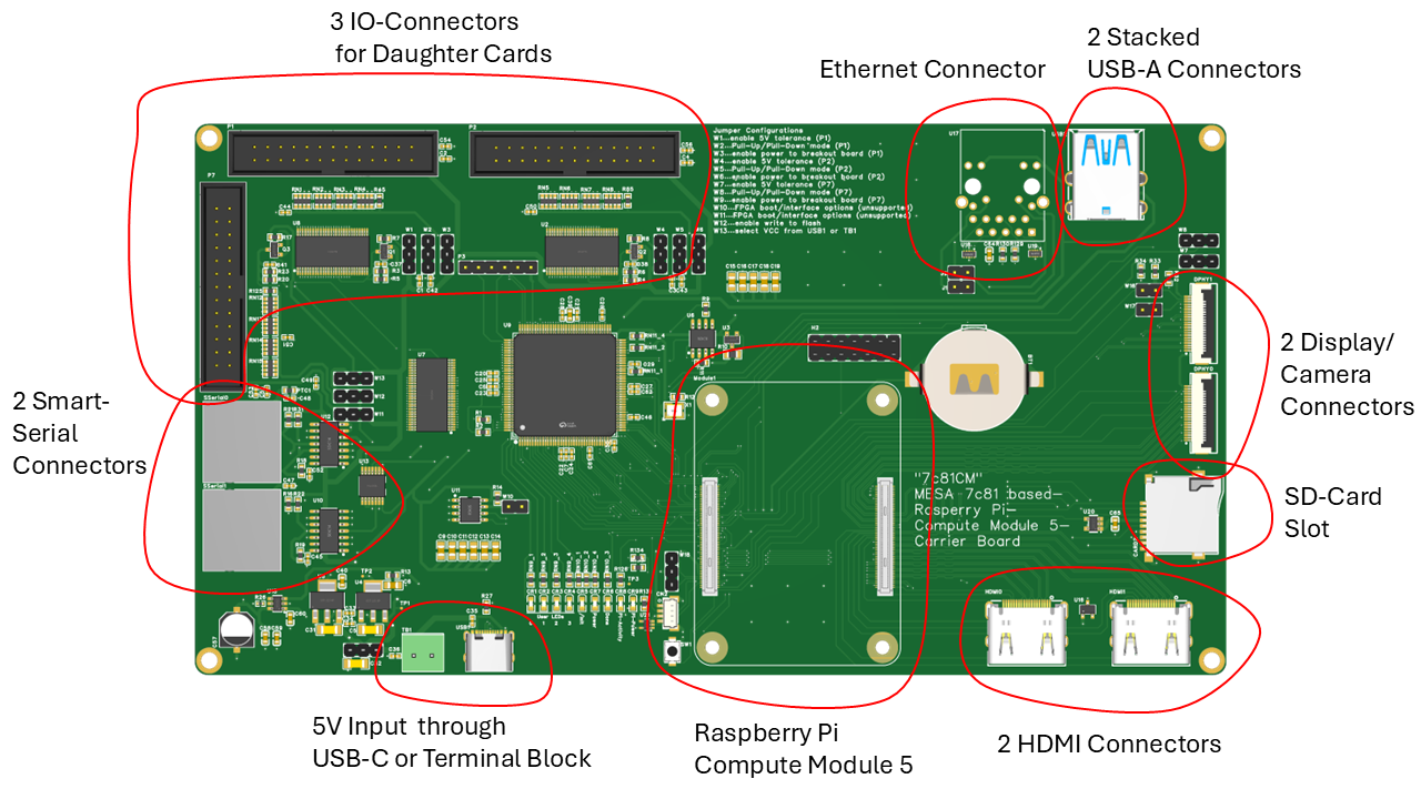
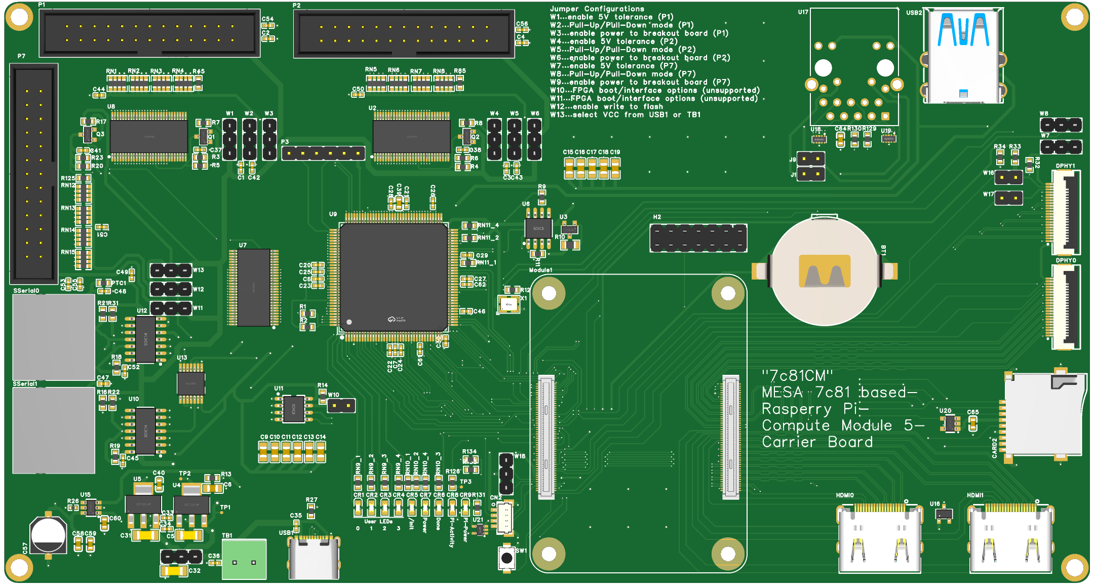
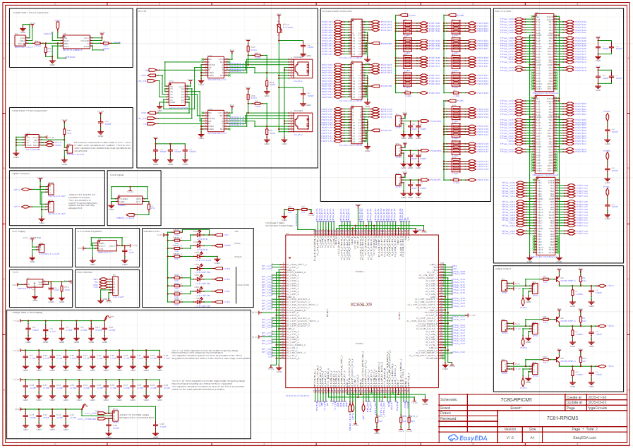
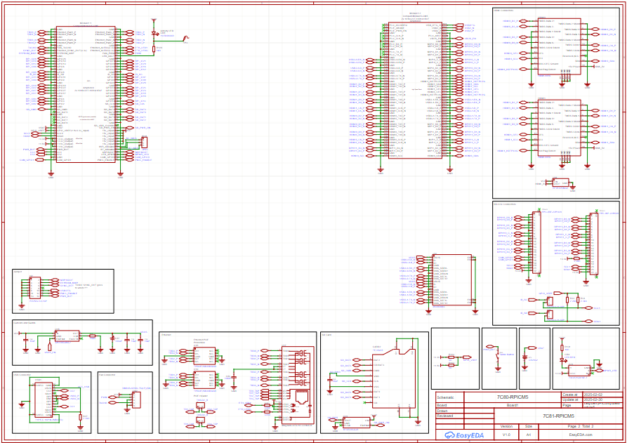
I made a custom version of the MESA Electronics 7c81 FPGA Card that I thought some of you might find interesting.
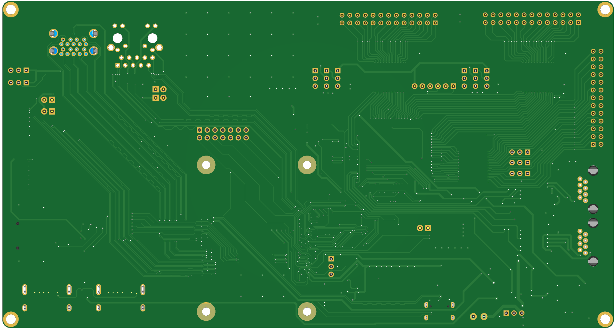
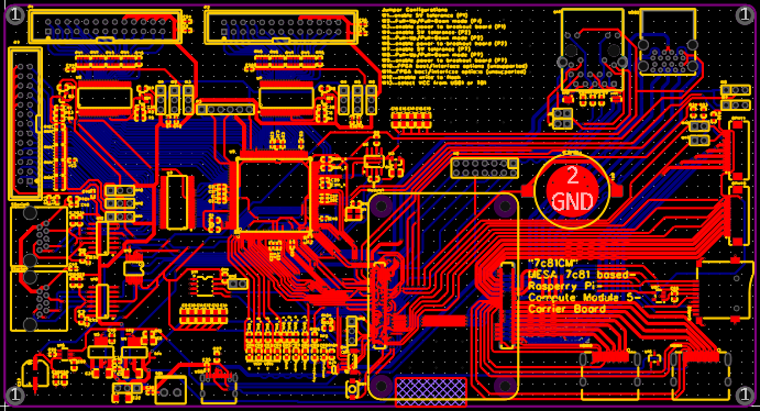
I've attached images of the progress I've made so far.
I haven't ordered the PCB yet, as I wanted to ask first, if any of you guys on here can find anything wrong with it. As I'm a student with limit budget I'd like to be a little more reassured that I'm not missing anything.
I used the
7c81 Schematics
found in this forum post and the schematics of the official
RPi CM5 IO-Board
to create my own schematics.
I have a few questions I haven't found a good answer for and I'd be happy to recieve constructive criticism on any part of the design.
The SPI0 Bus of the RPi (SDA0, SCL0) is shared by the Serial Flash for the FPGA and one of the MIPI DSI/CSI-2 FPC connectors. Will this cause conflicts?
I wasn't able to avoid routing traces under the FPGA, will this be likely to cause problems or will I be able to get away with it?
Is it a good idea to ground pour the top and bottom signal layers of the 4 layer stackup, if I'm already using the two inner layers as ground planes?
I can't advise on your PCB design, but I think this looks like a nice idea.
I have occasionally thought that there should be a niche for a similar board, but with on-board stepper drivers (Trinamic or some other serially-controlled driver)
That would, of course, need a dedicated HAL driver, but those can be surprisingly straightforward.
I would have brought the JTAG signals out for initial programming of the FPGA and not shared the serial flash signals.
May sound cumbersome but programming only needs to be done once via JTAG, after that mesa flash does the job fine.
I've thought along the lines of Andy that it would be an interesting project.
From my 7c81 clone experience I think there is the possibility of being able to bring out an extra 17 pin port, for a total of 68 io. Tho this would require firmware changes, new custom board name and and such. Also I made some changes to mesa flash and the driver to suit.
One thing I have noted with the RPi5 is that it's more forgiving in relation the SPI cable length and "messiness", IE it will tolerate longer DuPont cables that an RPi4 would. I thought I would just mention this.
Apart from not having the skill to design a board to suit, nor anyone to help during the process is that I like having the boards seperate, just in case my butter fingers cause one the voltage translation chips to blow a smoke valve and damage the PCB. Honestly this is likely to be a rare event.
On the whole good luck and keep us informed. If you have any questions regarding the Linuxcnc image I'm happy to help.
Normally on a 4 layer card you do not need top or bottom fills
unless for heat sinking or shielding. You do need to be a bit careful
about the 3.3V/1.2V plane cut/bypass capacitors/supply inductance,
and some under FPGA filling of the VCC plane can help here.
The SPI clock will be the fussiest signal so if you are routing it
a long distance, it may need parallel termination at the end of the trace
(series termination does not work with two endpoints)
I am liking the look of this board. Did you do this in easyeda?
Suggestion, add the rpi 40pin header. Aside from being able to add stuff rpi side, I find it valuable for debugging the MCU/FPGA side of the board using a regular rpi without having to keep removing a cm module and you can use it as a backup incase you damage the 100pin hirose connectors or theres another RPi/chip shortage