Hello, once more.
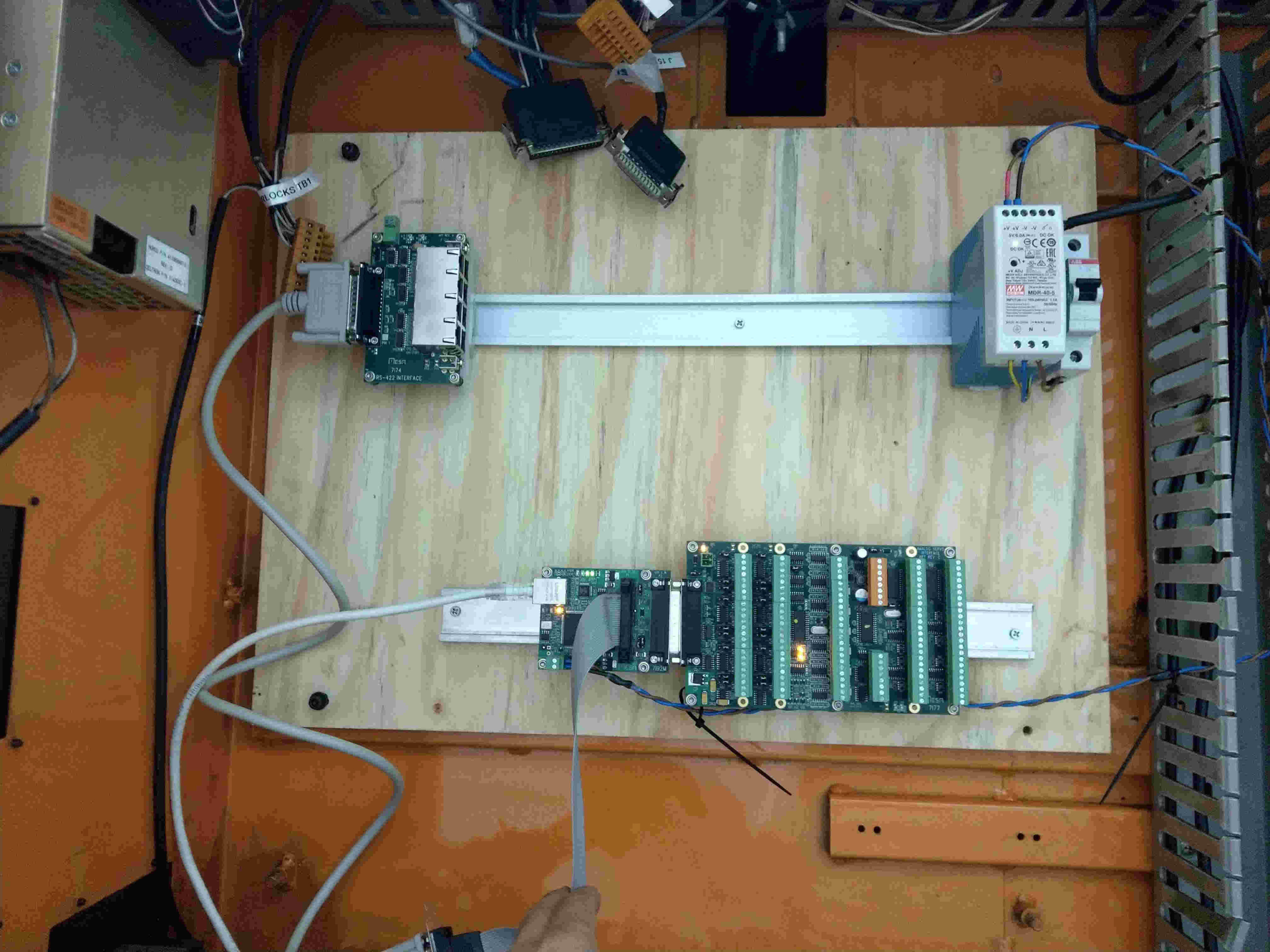
It’s getting late down here and I'm beginning to realize that I’m might be missing basic electrical knowledge to understand how things inside my cnc machine were working… Having as a guidance the initial wiring diagrams from the Hurco, I’m trying to understand how to connect my X/Y/Z limit switches to the 7i77D.
Apologies if what I’m trying to achieve is not clear enough.
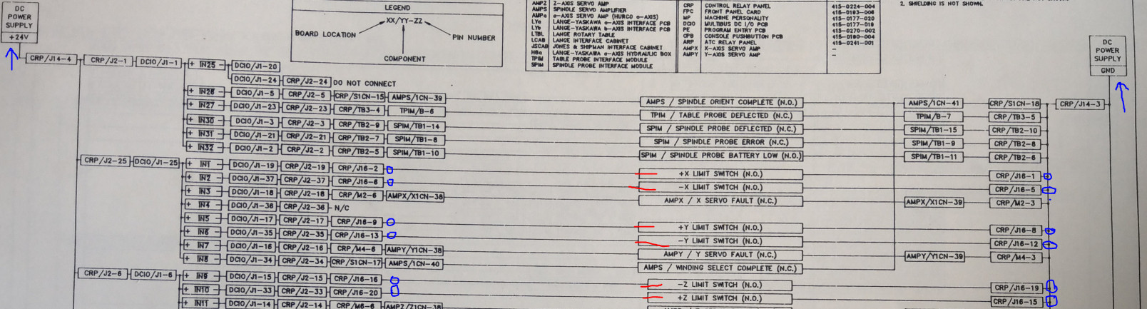
Starting with a 24V from the DC power and passing through a lot of “junctions” within the old Hurco controller, we end up in connector “J16”.
J16, pin 2 was to +X Limit switch (N.O.) and then ends up in J16 pin 1.
J16, pin 6 was to +X Limit switch (N.O.) and then ends up in J16 pin 5.
J16, pin 9 was to +Y Limit switch (N.O.) and then ends up in J16 pin 8.
J16, pin 13 was to -Y Limit switch (N.O.) and then ends up in J16 pin 12.
J16, pin 16 was to -Z Limit switch (N.O.) and then ends up in J16 pin 19.
J16, pin 20 was to +Z Limit switch (N.O.) and then ends up in J16 pin 15.
All end pins are to be grounded back to the power supply.Photo of the wiring diagram is attached.
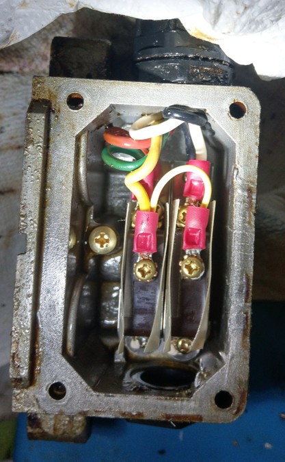
Now, my limit switches are “Micro LDV5202”, there are fairly limited datasheets, so I have opened up one to have a look (specifically the Y-axis). These are double pins but with two separate limits switches within (one hits the negative and the other the positive ends of travel). All three axis have the same limit switches, so I would have to assume that their wiring is identical. Inside the switch there are in total 5 cables, one cable is shared within the two limit switches. I have found that the limit switches inside are “Honewell AS-J215” but no more information is available…So basically we have the following connection in each limit switch:
Switch 1 -> Yellow, Green, and Red.
Switch 2 -> Yellow, White, and Black.
Photo of the opened up casing of the limit switches attached.
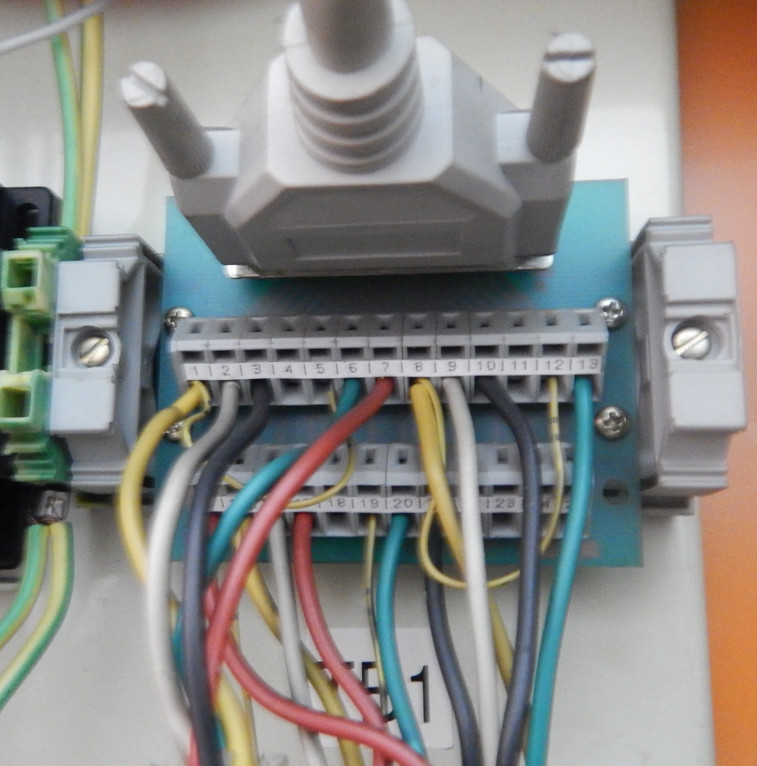
Going back to the Hurco, in the “TB1” where all these wires end up, I see the how the connections are being done and by combining the initial wiring diagram of the connector J16 I end up with the following for Y-axis only:
24V to J16, pin 9 (WHITE cable) was to +Y Limit switch (N.O.) and then ends up in J16 pin 8 (YELLOW cable) to ground.
24V to J16, pin 13 (GREEN cable) was to -Y Limit switch (N.O.) and then ends up in J16 pin 12 (YELLOW cable) to ground.
I can’t find any information about the RED and BLACK cable which comes from the limit switches, or any information in the wiring diagrams about pins 7 and 10 which are terminated.
Photo of the connector attached.
Now the questions:
a) Are the any ideas, how to check what is the red and black cables? And whether these are needed somehow.
b) If I had to assume, I would put 24V on the specified pins (WHITE and GREEN) and return the end pins (which previously were going to ground) as an input to my 7i77. Will that work, or I will end up burning my 7i77 since I can’t control how much amps will go through the limit switches?
If I’m asking something that has been done again, please point me to the right direction.