New CAM tutorial with Free Software
- laurent_parti
- Offline
- New Member
-

Less
More
- Posts: 10
- Thank you received: 11
08 Apr 2018 17:16 - 08 Apr 2018 17:18 #108611
by laurent_parti
New CAM tutorial with Free Software was created by laurent_parti
Hi all,
When I started CNC I spent a lot of time to find an open source CAM software.
Hope this tuto will help you guys:
When I started CNC I spent a lot of time to find an open source CAM software.
Hope this tuto will help you guys:
Last edit: 08 Apr 2018 17:18 by laurent_parti.
The following user(s) said Thank You: andypugh, hatch789, tommylight, zack
Please Log in or Create an account to join the conversation.
- tommylight
-

- Offline
- Moderator
-

Less
More
- Posts: 21619
- Thank you received: 7383
28 Apr 2018 21:30 #109771
by tommylight
Replied by tommylight on topic New CAM tutorial with Free Software
Took a quick look through it and it looks nicely done.
Thank you.
Thank you.
Please Log in or Create an account to join the conversation.
- hatch789
-

- Offline
- Premium Member
-

Less
More
- Posts: 143
- Thank you received: 0
29 Oct 2018 19:00 #119606
by hatch789
Replied by hatch789 on topic New CAM tutorial with Free Software
So I have used LinuxCNC for a few years though I was using it ONLY with pre-programmed .job and .ngc files from other people and was doing some rudamentary raw gcode myself to do very simple jobs.
Now I have a good CAD program (OnShape) that I can use to make accurate 3D parts and extract them. But I want to take the next step and start learning how to go from those parts in CAD to a real part or tool-path in CNC.
I have done quite a bit of work with 3D printers and am becoming pretty good with that technology but that's additive and this is subtractive. With my 3D printer stuff I merely extract the part I want slice it up and print it. Done. (yes I over-simplified it ...I know).
With my CNC mill I'm sort-of left with a gap. So here's an example of a real project need. I have a simple U-Channel of aluminum and I need to accurately reproduce holes in many of these parts. I'd like to clamp the U-Channel in my vice and jog to (about) the center of the piece. Drill 3 holes with CNC that are accurate and then 2 cuts through the sidewalls. Pretty simple --or so I thought.
I have the part and holes all exported from my OnShape program but the CAM programs I am trying see it as a whole piece. Kinda like my 3D printer and it's trying to make the whole damn thing out of a block of material I guess?
I just want it to do the holes from my start point (zero). So I need help. I feel like I'm just missing something simple here. I'm at work now but I'll watch this tutorial when I get home and see if it helps.
I would also like a good free CAM recommendataion. I was hoping this video would recommend one but I don't see it posted in the comments. Any help is greatly appreciated.
Please Log in or Create an account to join the conversation.
- alan_3301
- Offline
- Premium Member
-
Less
More
- Posts: 136
- Thank you received: 22
29 Oct 2018 20:11 - 29 Oct 2018 20:11 #119616
by alan_3301
Replied by alan_3301 on topic New CAM tutorial with Free Software
They have free licenses for autodesk fusion 360. I import cad designs from another software, then run the toolpaths in it.
In any cam software you will need to define an origin. Then in linuxcnc, you would jog to that point, and touch off to 0,0.
I didn't see any video or tutorial posted in your message. -- I see now that it's in the top message. oops.
In any cam software you will need to define an origin. Then in linuxcnc, you would jog to that point, and touch off to 0,0.
I didn't see any video or tutorial posted in your message. -- I see now that it's in the top message. oops.
Last edit: 29 Oct 2018 20:11 by alan_3301.
Please Log in or Create an account to join the conversation.
- hatch789
-
- Offline
- Premium Member
-
Less
More
- Posts: 143
- Thank you received: 0
29 Oct 2018 20:26 #119618
by hatch789
Replied by hatch789 on topic New CAM tutorial with Free Software
Thank you Alan,
So it's just the toolpath's part I need to run to get it to do the holes only? I keep getting a toolpath end result that clearly shows it machining the entire U-Channel out and all I want is the blasted holes. LOL
Adding complication to the mix I only have X & Y CNC on my machine. Z is manual so I'll have to pause for manual Z movements in this case. Hopefully that should be pretty simple.
Please Log in or Create an account to join the conversation.
- alan_3301
- Offline
- Premium Member
-
Less
More
- Posts: 136
- Thank you received: 22
29 Oct 2018 20:31 #119619
by alan_3301
Replied by alan_3301 on topic New CAM tutorial with Free Software
If that is the case, it would probably be easier to just use the MDI tab to enter your locations manually.
Jog the machine to a place that will be your 0,0 reference. Then touch off x and y axes, so that the display reads 0 for both. Then you can move each axis as you need with gcode commands.
These are just drilled hole locations, or you need to do a slot?
Jog the machine to a place that will be your 0,0 reference. Then touch off x and y axes, so that the display reads 0 for both. Then you can move each axis as you need with gcode commands.
These are just drilled hole locations, or you need to do a slot?
Please Log in or Create an account to join the conversation.
- andypugh
-

- Offline
- Moderator
-
Less
More
- Posts: 19861
- Thank you received: 4636
31 Oct 2018 11:26 #119700
by andypugh
You either need to
a) Tell the CAM system that you are starting with a channel (if your CAM supports importing complex stock geometry, many just allow cuboids or cylinders).
b) Select only the features you want to machine when creating the paths.
For a channel you can probably set the top-height for the CAM to the bottom of the channel and the safe-height high enough to clear the sides. You probably also want to draw some "exclude" areas to protect the sides from the cutter.
You haven't said which CAM system you are using with OnShape?
Replied by andypugh on topic New CAM tutorial with Free Software
So it's just the toolpath's part I need to run to get it to do the holes only? I keep getting a toolpath end result that clearly shows it machining the entire U-Channel out and all I want is the blasted holes. LOL
You either need to
a) Tell the CAM system that you are starting with a channel (if your CAM supports importing complex stock geometry, many just allow cuboids or cylinders).
b) Select only the features you want to machine when creating the paths.
For a channel you can probably set the top-height for the CAM to the bottom of the channel and the safe-height high enough to clear the sides. You probably also want to draw some "exclude" areas to protect the sides from the cutter.
You haven't said which CAM system you are using with OnShape?
Please Log in or Create an account to join the conversation.
- hatch789
-
- Offline
- Premium Member
-
Less
More
- Posts: 143
- Thank you received: 0
12 Nov 2018 14:56 - 12 Nov 2018 14:56 #120490
by hatch789
Replied by hatch789 on topic New CAM tutorial with Free Software
Hi Guys,
My apologies to Alan and Andy for not replying sooner ...we were out of town for a while. Anyway back to this very important stuff. If I didn't say it before I need this to be reproducible so if I do MDI movements, I would have to save them for later and I would have to learn CNC codes a lot more since I need to do circles and stuff, pause to adjust my Z (I only have X & Y CNC) and then the harder part is these slots which are at odd angles.
So that is why I was looking for a CAM package, but to your question Andi, I don't have one. I just got onto here last month to start looking for what I should use. I am good with 3D printing (as previously mentioned) but those programs take my CAD file and build the entire part from scratch. In this case I am starting with something. Let's say a block and I'm trying to tell it to just do these particular toolpaths.
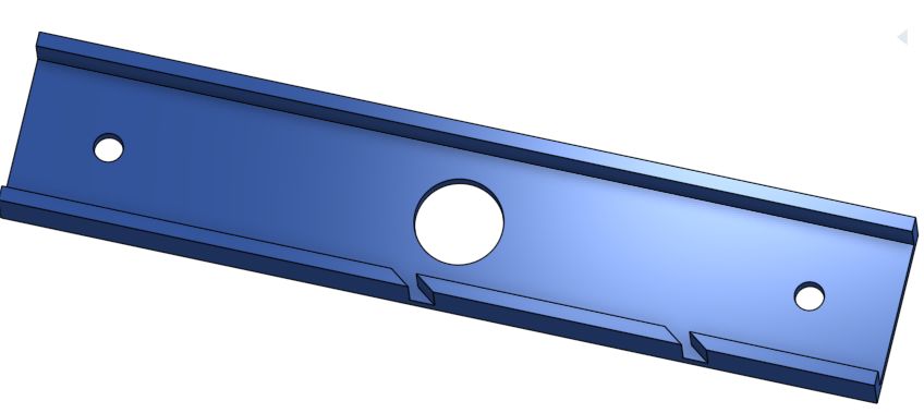
I get that I can zero the machine at a point close to the center and I'll be good. Other than that slight variance I need my parts to be identical so that's why I want to do this with CNC. It's simply making 3 holes in my U channel and then doing some slots. Here are 2 images of what I'm talking about (attached).
So this is why I want to use CAM so that if I change my part I don't have to go through the pain of using MDI all over again.

My apologies to Alan and Andy for not replying sooner ...we were out of town for a while. Anyway back to this very important stuff. If I didn't say it before I need this to be reproducible so if I do MDI movements, I would have to save them for later and I would have to learn CNC codes a lot more since I need to do circles and stuff, pause to adjust my Z (I only have X & Y CNC) and then the harder part is these slots which are at odd angles.
So that is why I was looking for a CAM package, but to your question Andi, I don't have one. I just got onto here last month to start looking for what I should use. I am good with 3D printing (as previously mentioned) but those programs take my CAD file and build the entire part from scratch. In this case I am starting with something. Let's say a block and I'm trying to tell it to just do these particular toolpaths.
I get that I can zero the machine at a point close to the center and I'll be good. Other than that slight variance I need my parts to be identical so that's why I want to do this with CNC. It's simply making 3 holes in my U channel and then doing some slots. Here are 2 images of what I'm talking about (attached).
So this is why I want to use CAM so that if I change my part I don't have to go through the pain of using MDI all over again.
Last edit: 12 Nov 2018 14:56 by hatch789.
Please Log in or Create an account to join the conversation.
- andypugh
-
- Offline
- Moderator
-
Less
More
- Posts: 19861
- Thank you received: 4636
12 Nov 2018 15:12 - 12 Nov 2018 15:13 #120492
by andypugh
Replied by andypugh on topic New CAM tutorial with Free Software
Actually, for those parts, I would write G-code by hand.
Each hole is something like:
Hand-coded will probably be more efficient than CAM as you can leave the circle centres as solid discs, which CAM packages tend not to do, instead machining out the entire circle.
Each hole is something like:
G0 X[100+20] Y0
G0 Z0
G3 F100 Z-6 I-20 P4
Hand-coded will probably be more efficient than CAM as you can leave the circle centres as solid discs, which CAM packages tend not to do, instead machining out the entire circle.
Last edit: 12 Nov 2018 15:13 by andypugh.
Please Log in or Create an account to join the conversation.
- hatch789
-
- Offline
- Premium Member
-
Less
More
- Posts: 143
- Thank you received: 0
12 Nov 2018 16:00 #120496
by hatch789
Replied by hatch789 on topic New CAM tutorial with Free Software
Hi Andy,
If it was just holes I would agree. I have done them before with hand-coding and it wasn't bad. But how do I accurately determine the gcode for my slots that have to be at a precise angle? I'm a bit confused by that.
Also is the P command used for "dwell" to let me move my spindle up or down before a next operation? Ideally in linuxcnc I'd like to require that I press a button on my joystick (which I can use to move my bed) before it continues on. This is a bit safer than simply pause for 4 seconds.
Please Log in or Create an account to join the conversation.
Time to create page: 0.154 seconds