DB25 breakout board
- brainwave
- Offline
- New Member
-

- Posts: 5
- Thank you received: 0
I am placing this really not as a question but because I found many questions about those cheap breakout boards online. So this might help someone.
I had a minimill running with one of the new TB6560 (V4, the fixed boards) and a Mesa 5i25 with Prob_RFX2 firmware (no additional daughterboard needed). Now I a migrating to a bigger mill, thus new stepper drivers, in my case DQ2722M and DQ860. The breakout board of course came with no instructions.
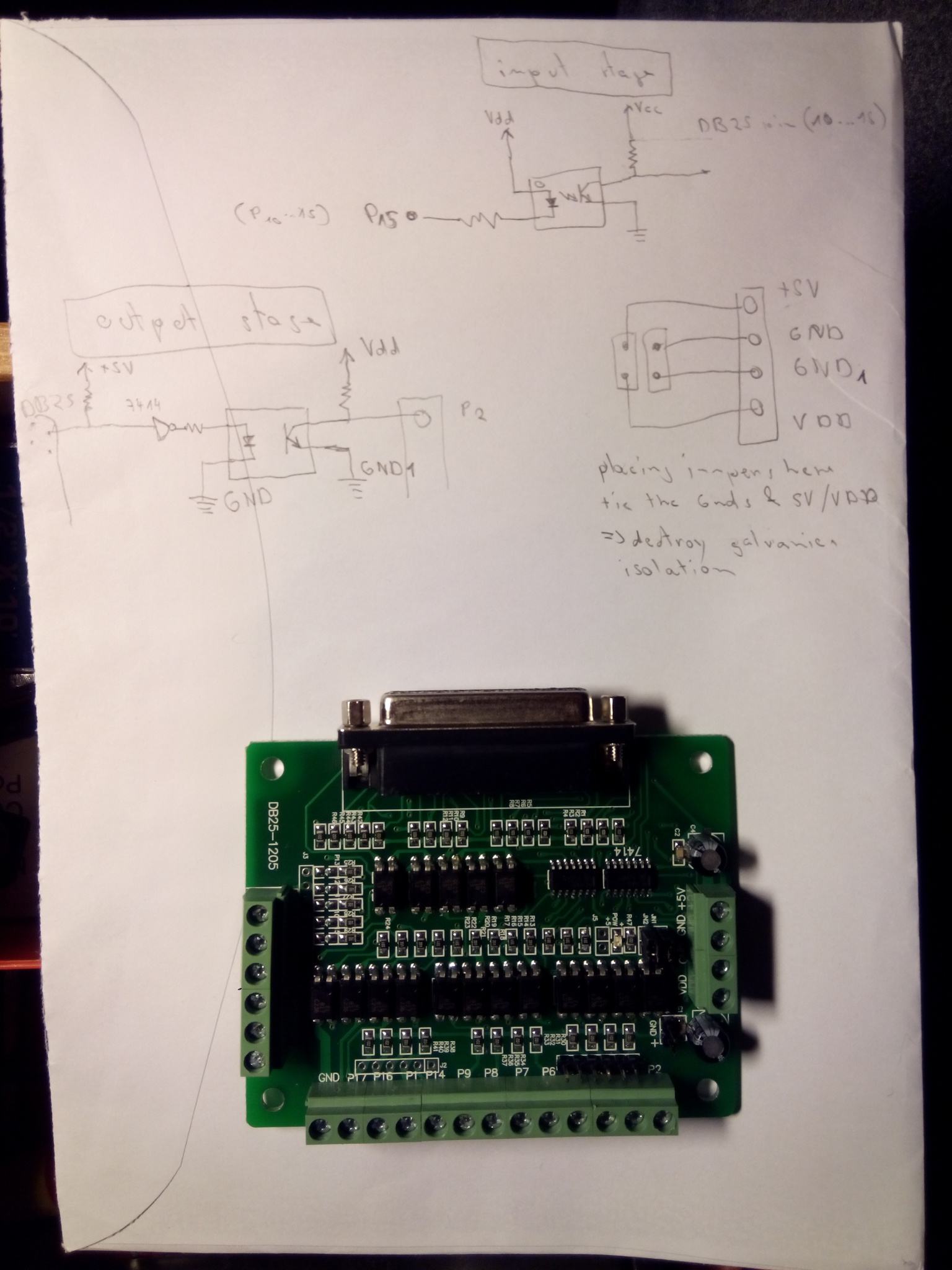
One thing I noticed that I think many people miss, is that the breakout board is supposed to isolate galvanically the computer from the power side, however the breakout board comes configured in a way that ties both sides ground and power supply ! Notice on the photo, the two jumpers close to the +5V, GND, GND, Vdd terminal. Those tie +5V with Vdd and the two GND together. The proper way to use such a board is to remove the jumpers, then provide +5V and ground from a separate PS or the internal PC power supply, then the other GND and Vdd connect to a second power supply (or one of the stepper supplies if it has 5V or more)
Another issue is wether the outputs are inverting or not. In my case, there are 7414 inverters after the parallel port.
The input and output stages are drawn in the photo attached.
I hope this will help somebody !
Please Log in or Create an account to join the conversation.
- bernie_nor
- Offline
- New Member
-
- Posts: 10
- Thank you received: 0
I have the same breakout board. And according to information found on the big interwebz it should be to slow to drive my stepper drivers at full microstepping. I upgraded the board by changing the opto-couplers for the step signals from EL817 (they are as cheep as they get) to TLP118. The TLP118 needs to be powered with +5V on the machine side of the galvanic barrier. With his modification I did run tests sending square pulses at 65kHz (max of my cheep ebay signal generator) and the shape is still nice and crisp with hardly any propagation delay.
Worth looking into if your not getting the speeds and performance you expect.
Cheers!
Bernie
Please Log in or Create an account to join the conversation.
- brainwave
- Offline
- New Member
-
- Posts: 5
- Thank you received: 0
Considering I am using a stepper driver that already has optocoupled inputs, I think it is best to remove the board's output optocouplers altogether and replace with npn transistors driven by 4.7k resistors. Going to test that out...
Please Log in or Create an account to join the conversation.
- bernie_nor
- Offline
- New Member
-
- Posts: 10
- Thank you received: 0
I've done a lot of research on speeding up the response time of this kind of opto couplers.To speed up the turn on time, one would want a small resistor giving a large forward current. But this would on the other end saturate the transistor making is slow on the turn off. To make the turn off quick one would want to have as large a resistor as possible. To get both you could go for the large resistor and place a capacitor in parallel. But replacing the opto coupler gives a improvement in the region of a ten fold over the optimized resistor/capacitor solution.
Sorry for this being a bit of topic, got carried away...
Cheers!
Bernie
Please Log in or Create an account to join the conversation.
- brainwave
- Offline
- New Member
-
- Posts: 5
- Thank you received: 0
Not sure I fully share your concern. The HC14 is driving a LED through the 330R resistor, not just the resistor to GND. The PC817 has a Vf (Forward voltage) of 1.2V typically (@20mA). This would give us a forward current in the region of 10-11mA. It's a bit high I agree. I would not have approved a solution like this at work, but on the other hand I'm not going to alter this on my BOB. If te HC is not capable of supplying the required power, it will just supply a bit less. Pushing a circuit to the end of the envelope like this reduces the expected lifetime (MTTF). I can live with that.
Correct, but that also means even slower rise times than what could be had with the EL817
I've done a lot of research on speeding up the response time of this kind of opto couplers.To speed up the turn on time, one would want a small resistor giving a large forward current. But this would on the other end saturate the transistor making is slow on the turn off. To make the turn off quick one would want to have as large a resistor as possible. To get both you could go for the large resistor and place a capacitor in parallel. But replacing the opto coupler gives a improvement in the region of a ten fold over the optimized resistor/capacitor solution.
yes, certainly, but I do not have faster optocouplers in my component pile, however I do have lots of 2n3904 so I can try that first
")
(and TLP118 are 0.5 - 1.2USD each while 2n3904 are less than half a cent each...)
Also, I do not care about the breakout board output optocouplers since the stepper drivers input are also optocoupled, so just a resistor / transistor combination should work a lot faster than resistor / opto / and pull up resistor.
That is the other point I noticed, there are 1k ohm pullup resistors after the breakout board optocouplers, which seem completely necessary if the output triggers an optocoupler, don't you think ?
Bruno
Please Log in or Create an account to join the conversation.
- brainwave
- Offline
- New Member
-
- Posts: 5
- Thank you received: 0
Please Log in or Create an account to join the conversation.
- bernie_nor
- Offline
- New Member
-
- Posts: 10
- Thank you received: 0
I've set up an LTspice simulation. I've played around with a paralell capacitor. I also tried to alter the load resistor (1k) to improve the turn off time of the opto, but I could not get much improvment.
LTspice is free and available from www.linear.com
Cheers!
Bernie
Please Log in or Create an account to join the conversation.
- kagouraki
-

- Offline
- Junior Member
-

- Posts: 31
- Thank you received: 4
Is there a way to use this board for input ? The pins 2-9 are my concern.
Thank you
Giorgos
Please Log in or Create an account to join the conversation.
- Todd Zuercher
-

- Away
- Platinum Member
-

- Posts: 4733
- Thank you received: 1449
Please Log in or Create an account to join the conversation.
- jtc
-
- Offline
- Premium Member
-

- Posts: 147
- Thank you received: 12
I think this documentation is for that board. P13 to P15 are inputs.
Please Log in or Create an account to join the conversation.