
- Posts: 711
- Thank you received: 0
Prototrak Plus Retrofit with Mesa 7i77 & 5i25 cards
9 years 6 months ago #91537
by new2linux
Replied by new2linux on topic Prototrak Plus Retrofit with Mesa 7i77 & 5i25 cards
thanks andypugh,
Is there a target value for the I & D, or just trial and error? Will work that in tomorrow.
Many thanks!
Is there a target value for the I & D, or just trial and error? Will work that in tomorrow.
Many thanks!
Please Log in to join the conversation.
- Todd Zuercher
- Offline
- Platinum Member
-

Less
More
- Posts: 4739
- Thank you received: 2
9 years 6 months ago #91539
by Todd Zuercher
Replied by Todd Zuercher on topic Prototrak Plus Retrofit with Mesa 7i77 & 5i25 cards
The target value is what ever works with your hardware, and configuration. There are too many variables to say x value should with work with y setup. That is why it is called "tuning" a servo. (it is a lot like tuning a musical instrument.)
Please Log in to join the conversation.
9 years 6 months ago #91549
by new2linux
Replied by new2linux on topic Prototrak Plus Retrofit with Mesa 7i77 & 5i25 cards
Many thanks!!
Just a small amount of I & D have made a big difference, the oscillation way down. I can see why its compared to instrument tuning. Now the linuxcnc computer is not by internet computer, there is the extra step involved now, to relay updates.
many thanks!!
Just a small amount of I & D have made a big difference, the oscillation way down. I can see why its compared to instrument tuning. Now the linuxcnc computer is not by internet computer, there is the extra step involved now, to relay updates.
many thanks!!
Please Log in to join the conversation.
9 years 6 months ago #91593
by new2linux
Replied by new2linux on topic Prototrak Plus Retrofit with Mesa 7i77 & 5i25 cards
Many thanks!!
The trace in hal scope, is there a specific shape, or say the beginning, the corners will or will not have a small spike up wards, just as it starts is acceptable or just tune it till the servo won"t over heat, and works well at most speeds. Trying to understand when to stop tuning.
thanks
The trace in hal scope, is there a specific shape, or say the beginning, the corners will or will not have a small spike up wards, just as it starts is acceptable or just tune it till the servo won"t over heat, and works well at most speeds. Trying to understand when to stop tuning.
thanks
Please Log in to join the conversation.
- Todd Zuercher
- Offline
- Platinum Member
-
Less
More
- Posts: 4739
- Thank you received: 2
9 years 6 months ago #91596
by Todd Zuercher
Replied by Todd Zuercher on topic Prototrak Plus Retrofit with Mesa 7i77 & 5i25 cards
Generally you want to minimize the amount of following error. Usually within about 3-5 encoder counts is about as good as you can get. (You'll have to calculate what distance 1 encoder count equals.) You should strive for a system that is at least quiet at rest and not oscillating at a aplitude. If the drive is bouncing back and forth constantly, it can quickly overheat itself and or the motor. This is usually a sign of to much of something, P, I, D... To much of these or an FF term can all lead to over shoot and cause these oscillations. It is also possible that the velocity loop in the drive may need tuned better.
Please Log in to join the conversation.

9 years 6 months ago #91597
by lakeweb
Replied by lakeweb on topic Prototrak Plus Retrofit with Mesa 7i77 & 5i25 cards
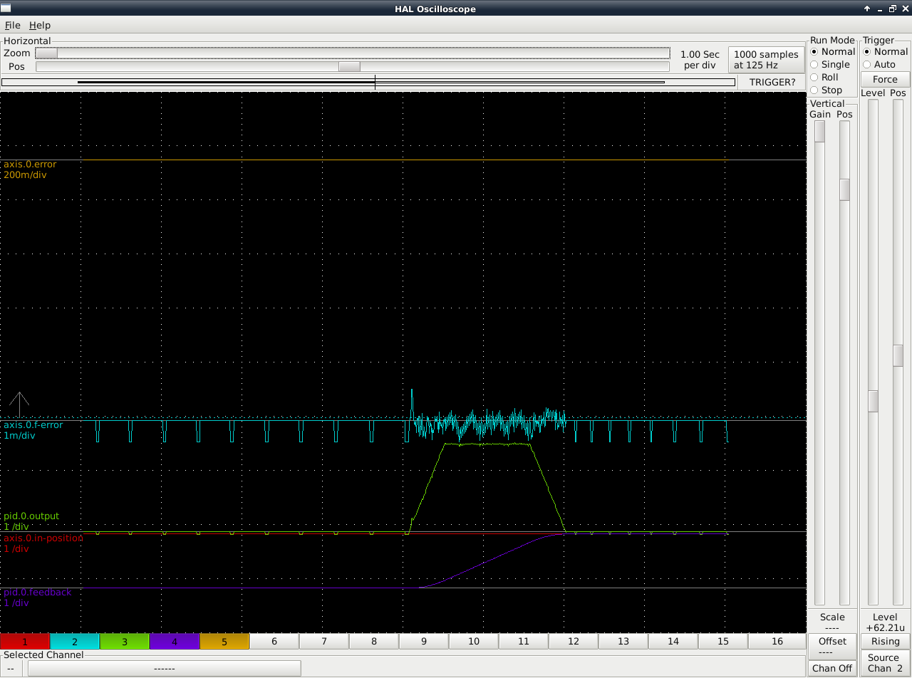
If you are using the likes of M1X1F5 in the command window, then you want to look at the hal trace axis.0.f.error. Note that the gain is set all the way up for this channel
from: Page Source
Best, Dan.
from: Page Source
Best, Dan.
Please Log in to join the conversation.
9 years 6 months ago #91667
by new2linux
Replied by new2linux on topic Prototrak Plus Retrofit with Mesa 7i77 & 5i25 cards
Todd Zuercher wrote: Generally you want to minimize the amount of following error. Usually within about 3-5 encoder counts is about as good as you can get. (You'll have to calculate what distance 1 encoder count equals.)
Todd Many thanks for your help! I see the DRO is as accurate as the ball screw pitch, it would appear. When you talk about "following error" is the (in my case a dip in the hal trace) amount it wants to over shoot the target? To calculate what 1 encoder count equals, I would 2000 count/quadrant(8000/rev); x .2 pitch of ball screw; 16 to 44 timing pulley ratio; and evaluate that way?
lakeweb, many thanks for your link to your project, looks great! Currently, my tuning has not enabled me to see (hal trace) screen like yours, but the 60"/min jog looks and sounds very very good, I started low several times and believe the settings are at the low end of what is ideal. No oscillating, noise or sluggishness, but not uniform with perfect symmetrical angled lines, mine goes (at 60"/min) high spike (not crazy) at beginning, almost level line (small amount of drop over long run) and drop (nearly vertical down) at end of run, with out going below starting datum. I tried to get screen shot but with no luck.
Many thanks!
Please Log in to join the conversation.
- Todd Zuercher
- Offline
- Platinum Member
-
Less
More
- Posts: 4739
- Thank you received: 2
9 years 6 months ago #91671
by Todd Zuercher
Replied by Todd Zuercher on topic Prototrak Plus Retrofit with Mesa 7i77 & 5i25 cards
Like in the picture of halscope posted by lakeweb above, he has a small spike of error of about 0.0005 at the beginning of the movement.
The distance moved by one encoder count will simply be the inverse of your encoder scale for that axis. (1/x)
Don't get discouraged, it can take a while to learn the feel for how to tune a servo. Especially if the drives you are tuning are torque and not velocity input.
It took me a long time and a lot of fiddling to get from this first picture to the 2nd (this is on a torque mode servo)
Attachment not found
Attachment not found
Please Log in to join the conversation.
9 years 6 months ago #91693
by new2linux
Replied by new2linux on topic Prototrak Plus Retrofit with Mesa 7i77 & 5i25 cards
Many thanks for the encouraging words!
So negative values are acceptable, (as in "I" in the 1st pic) as well? My system is set up as "torque mode" not velocity mode, so my hope is I can refine the tuning more w/o great difficulty, to get a hal trace similar to the one in bottom pic.
Thanks for all the great help!
So negative values are acceptable, (as in "I" in the 1st pic) as well? My system is set up as "torque mode" not velocity mode, so my hope is I can refine the tuning more w/o great difficulty, to get a hal trace similar to the one in bottom pic.
Thanks for all the great help!
Please Log in to join the conversation.
9 years 6 months ago #91700
by PCW
Replied by PCW on topic Prototrak Plus Retrofit with Mesa 7i77 & 5i25 cards
Negative I does not work safely with the PID component
(nor does it make any sense for a velocity or torque mode servo)
Velocity mode servos are tuned chiefly with P and FF1
Torque mode servo need mainly P,I,D and FF2
Torque mode servo tuning will benefit from running the servo loop faster than
LinuxCNCs default 1KHz and using a dual PID loop (position loop around a velocity loop)
Please Log in to join the conversation.
Time to create page: 0.119 seconds