Review Request for Arc Volt Sensor Schematic
- alangibson
- Offline
- Premium Member
-

Less
More
- Posts: 95
- Thank you received: 36
25 Mar 2026 09:58 - 26 Mar 2026 12:40 #344703
by alangibson
Review Request for Arc Volt Sensor Schematic was created by alangibson
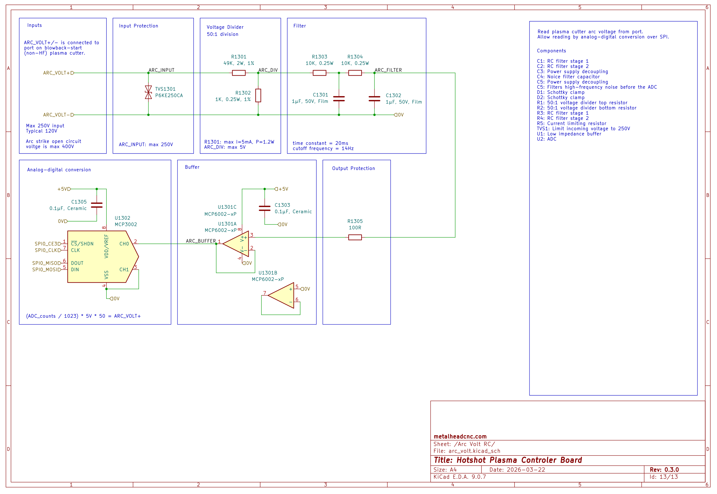
Hi all. I've been playing with a design for a board that will allow me to read arc voltage with a Raspberry Pi. I think I've got something that will plausibly work. I'd appreciate a review of the attached schematic because circuit design is not my core competency.
Here's a quick tour:
1. Inputs are expected to be connected to the arc volt port of a blowback-start plasma power supply.
2. Input voltage is limited to 250V by a TVS diode
3. Voltage is divided 50:1
4. RCRC filter limits frequency to 14Hz
5. Raspberry Pi reads divided voltage via ADC
Thanks!
Here's a quick tour:
1. Inputs are expected to be connected to the arc volt port of a blowback-start plasma power supply.
2. Input voltage is limited to 250V by a TVS diode
3. Voltage is divided 50:1
4. RCRC filter limits frequency to 14Hz
5. Raspberry Pi reads divided voltage via ADC
Thanks!
Attachments:
Last edit: 26 Mar 2026 12:40 by alangibson.
Please Log in or Create an account to join the conversation.
- andypugh
-

- Offline
- Moderator
-

Less
More
- Posts: 19863
- Thank you received: 4636
25 Mar 2026 12:48 #344718
by andypugh
Replied by andypugh on topic Review Request for Arc Volt Sensor Schematic
It says 400V Open Circuit Voltage, but you have a 250V TVS.
Maybe the TVS can go after the voltage divider? Or have a 500V one and a second lower voltage one after the divider. I think that with the TVS after the divider the divider would limit the current through it, which might work better.
You should probably put an optical isolator on the SPI lines from the ADC, just in case things do go wrong on your HV board.
The following user(s) said Thank You: tommylight
Please Log in or Create an account to join the conversation.
- Hakan
- Offline
- Platinum Member
-

Less
More
- Posts: 1317
- Thank you received: 453
25 Mar 2026 14:59 - 25 Mar 2026 15:20 #344721
by Hakan
Replied by Hakan on topic Review Request for Arc Volt Sensor Schematic
Arc voltage is DCEN, that is, between -400V and 0V.
The torch is negative, ground is positive.
Not saying that the below is correct. It has worked for me for many hours though.
github.com/MetalMusings/MyOwnEtherCATDev...in/Cards/THTIC/Kicad
The torch is negative, ground is positive.
Not saying that the below is correct. It has worked for me for many hours though.
github.com/MetalMusings/MyOwnEtherCATDev...in/Cards/THTIC/Kicad
Attachments:
Last edit: 25 Mar 2026 15:20 by Hakan.
The following user(s) said Thank You: tommylight
Please Log in or Create an account to join the conversation.
- alangibson
- Offline
- Premium Member
-
Less
More
- Posts: 95
- Thank you received: 36
25 Mar 2026 20:59 #344739
by alangibson
Replied by alangibson on topic Review Request for Arc Volt Sensor Schematic
My intention with the TVS was to limit input voltage to 250V. The ADC expects 0-5V range, and voltage division is 50:1, so anything above 250V is out of range.
In reality 250V is way high for a cutting voltage. I just came up with it by working backwards from the ADC voltage range.
Does that make sense?
Optoisolators are a good idea. I was planning on the TVS limiting the voltage, but I guess it's always possible that someone would hook this board up to a HF start torch.
Please Log in or Create an account to join the conversation.
- alangibson
- Offline
- Premium Member
-
Less
More
- Posts: 95
- Thank you received: 36
25 Mar 2026 21:35 #344742
by alangibson
Replied by alangibson on topic Review Request for Arc Volt Sensor Schematic
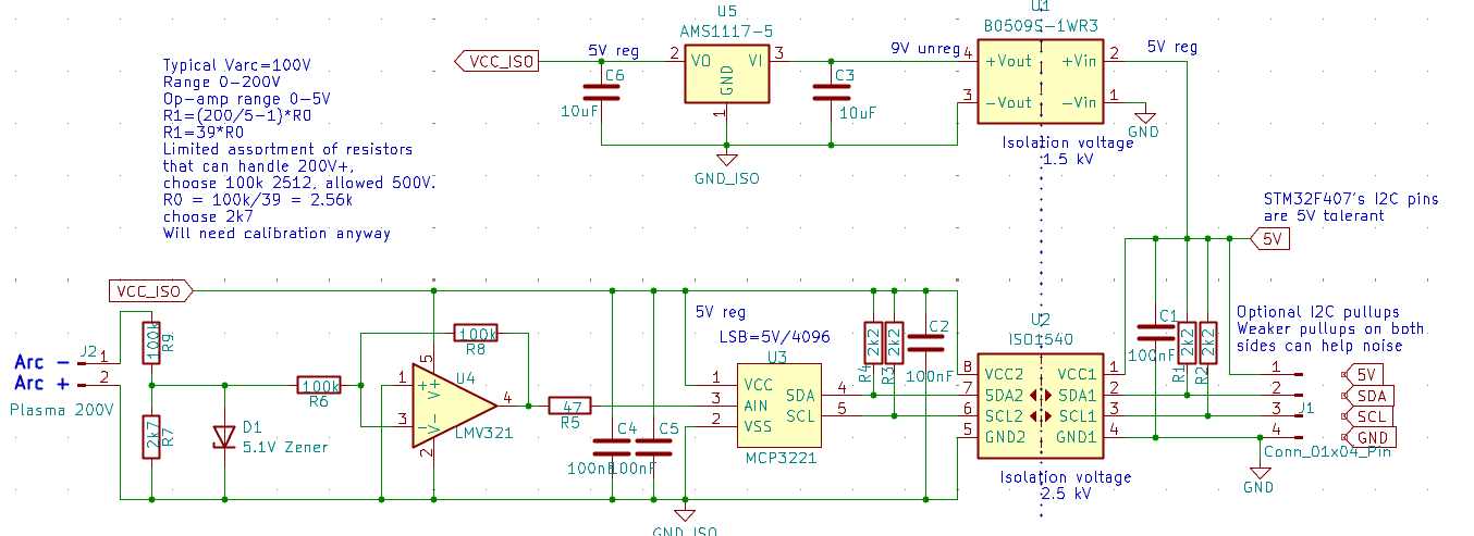
Thanks for the schematic. I wish I had found this a while ago.
I like how you use isolated and regulated voltage. I need to see if I can find a single component that does that.
> The torch is negative, ground is positive.
Ah right. I forgot that. Is that why U4 is inverted?
I took a stab at dissecting your schematic. This is what I got:
Voltage source
5V: Common 5VDC power source
U1: 1W Isolated DC-DC 9V out; Isolation 1.5k VDC/min
C3: Decoupling
U5: 5V LDO voltage regulator
C3: Decoupling
VCC_ISO: Isolated 5VDC
Input stage
R7,R9: Voltage divider, 38:1 ratio
D1: Limit input to max 5V
R6: Current limiting
U4: Voltage buffer (inverted ?)
R8: ?
R5: Current limiting?
C4: Decoupling?
C5: Decoupling?
U3: ADC with 12C output
R4: Pull-up resistor
R5: Pull-up resistor
C2: Decoupling?
Output stage
U2: I2C isolator; Isolation 2.5-kVrms
C1: Decoupling?
R1: Pull-up resistor
R2: Pull-up resistor
Please Log in or Create an account to join the conversation.
- tommylight
-

- Offline
- Moderator
-
Less
More
- Posts: 21658
- Thank you received: 7400
25 Mar 2026 23:17 #344745
by tommylight
-
Personally, i have a strict policy of doing the voltage divider using 3 resistors, always, saves a lot of headache in case of mishaps or wires shorts or any of plasma wires touching ground or machine.
Example, in case of Hakan's schematics, i would use a 2K7 in the middle of two 50K. The other side of both 50K would go to plasma arc voltage, and the measuring would be done on the 2K7.
Replied by tommylight on topic Review Request for Arc Volt Sensor Schematic
OK, but you must also add resistors in front of it, or it will blow up the first instance the voltage goes above 250V.My intention with the TVS was to limit input voltage to 250V.
-
Personally, i have a strict policy of doing the voltage divider using 3 resistors, always, saves a lot of headache in case of mishaps or wires shorts or any of plasma wires touching ground or machine.
Example, in case of Hakan's schematics, i would use a 2K7 in the middle of two 50K. The other side of both 50K would go to plasma arc voltage, and the measuring would be done on the 2K7.
Please Log in or Create an account to join the conversation.
- Hakan
- Offline
- Platinum Member
-
Less
More
- Posts: 1317
- Thank you received: 453
26 Mar 2026 01:23 #344747
by Hakan
Replied by Hakan on topic Review Request for Arc Volt Sensor Schematic
Yes, inverting and decoupling.
Wouldn't be surprised if there is a similar isolated SPI component.
Best if the ADC has some kind of free run mode. Otherwise the reading of a value can take too much time.
Was looking for a new value every millisecond, with as many bits of resolution as possible.
Have also used ADS1014 with similar good result.
Please Log in or Create an account to join the conversation.
- tommylight
-
- Offline
- Moderator
-
Less
More
- Posts: 21658
- Thank you received: 7400
26 Mar 2026 02:05 #344748
by tommylight
Replied by tommylight on topic Review Request for Arc Volt Sensor Schematic
I have these:
www.ti.com/product/LM331
but i never bothered to use them as the time is worth more than the price of THCAD.
Easy to use and can be plugged to parallel port with a single optocoupler.
www.ti.com/product/LM331
but i never bothered to use them as the time is worth more than the price of THCAD.
Easy to use and can be plugged to parallel port with a single optocoupler.
Please Log in or Create an account to join the conversation.
- alangibson
- Offline
- Premium Member
-
Less
More
- Posts: 95
- Thank you received: 36
26 Mar 2026 12:39 #344769
by alangibson
Replied by alangibson on topic Review Request for Arc Volt Sensor Schematic
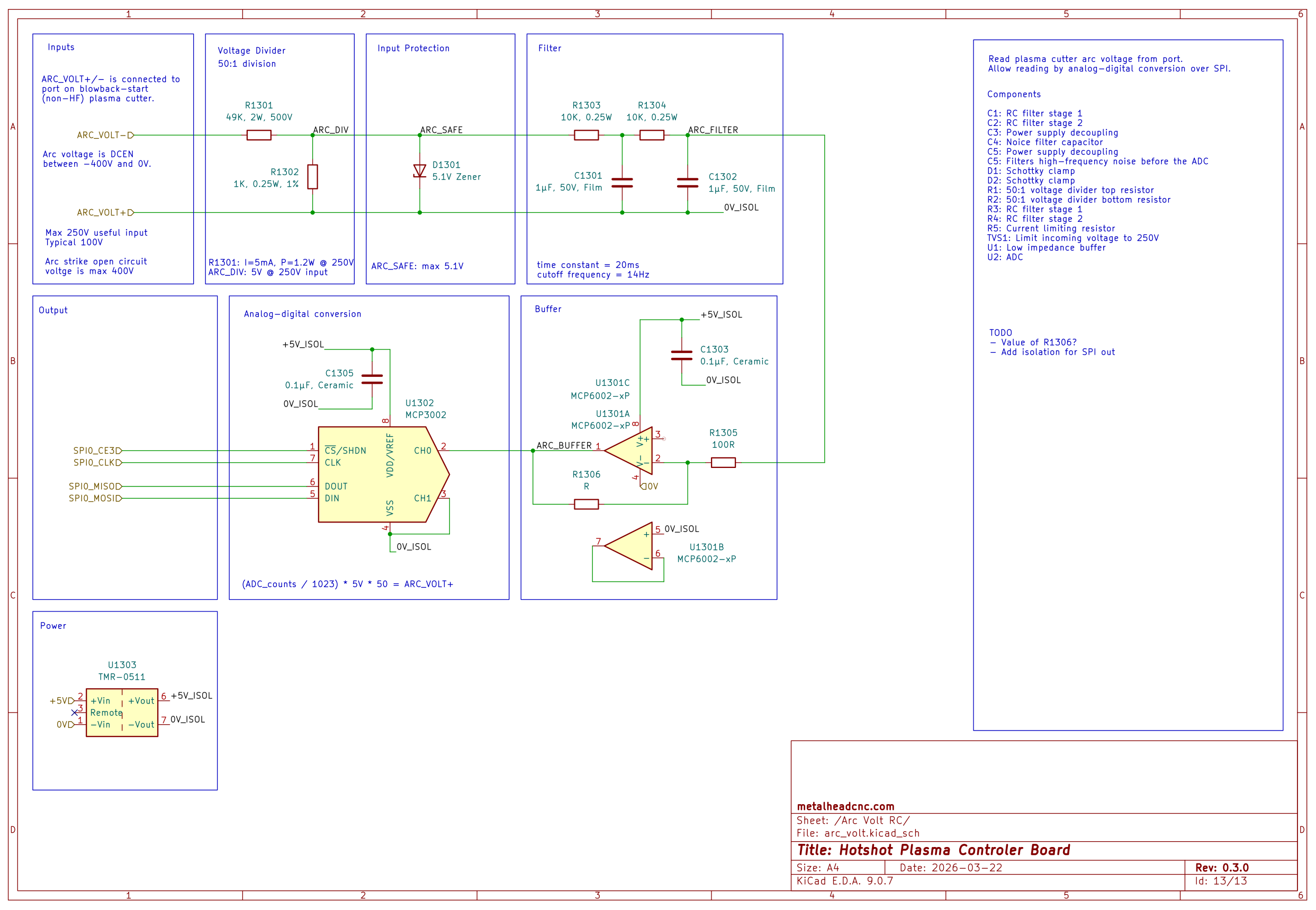
I moved the voltage divider to the first stage and put a zener after it for overvoltage protection like Hakan.
@tommylight: Do you have a schematic you can share that shows how you use 3 resistors for voltage division. I'm having trouble visualizing your description.
Here's where I'm at right now. I need to add SPI isolation. That's going to be the biggest stage of all because there aren't any good through-hole all in one solutions like there are for SMD.
Attachments:
Please Log in or Create an account to join the conversation.
- Hakan
- Offline
- Platinum Member
-
Less
More
- Posts: 1317
- Thank you received: 453
27 Mar 2026 08:15 #344816
by Hakan
Replied by Hakan on topic Review Request for Arc Volt Sensor Schematic
I also wonder about the 2 50k resistors.
Good find on the regulated TMR-0511.
I looked at the output of the isolated power supply I use. I wasn't terrible, almost ok but not totally stable.
Why the filter step? HF?
Good find on the regulated TMR-0511.
I looked at the output of the isolated power supply I use. I wasn't terrible, almost ok but not totally stable.
Why the filter step? HF?
Please Log in or Create an account to join the conversation.
Moderators: snowgoer540
Time to create page: 0.190 seconds